8
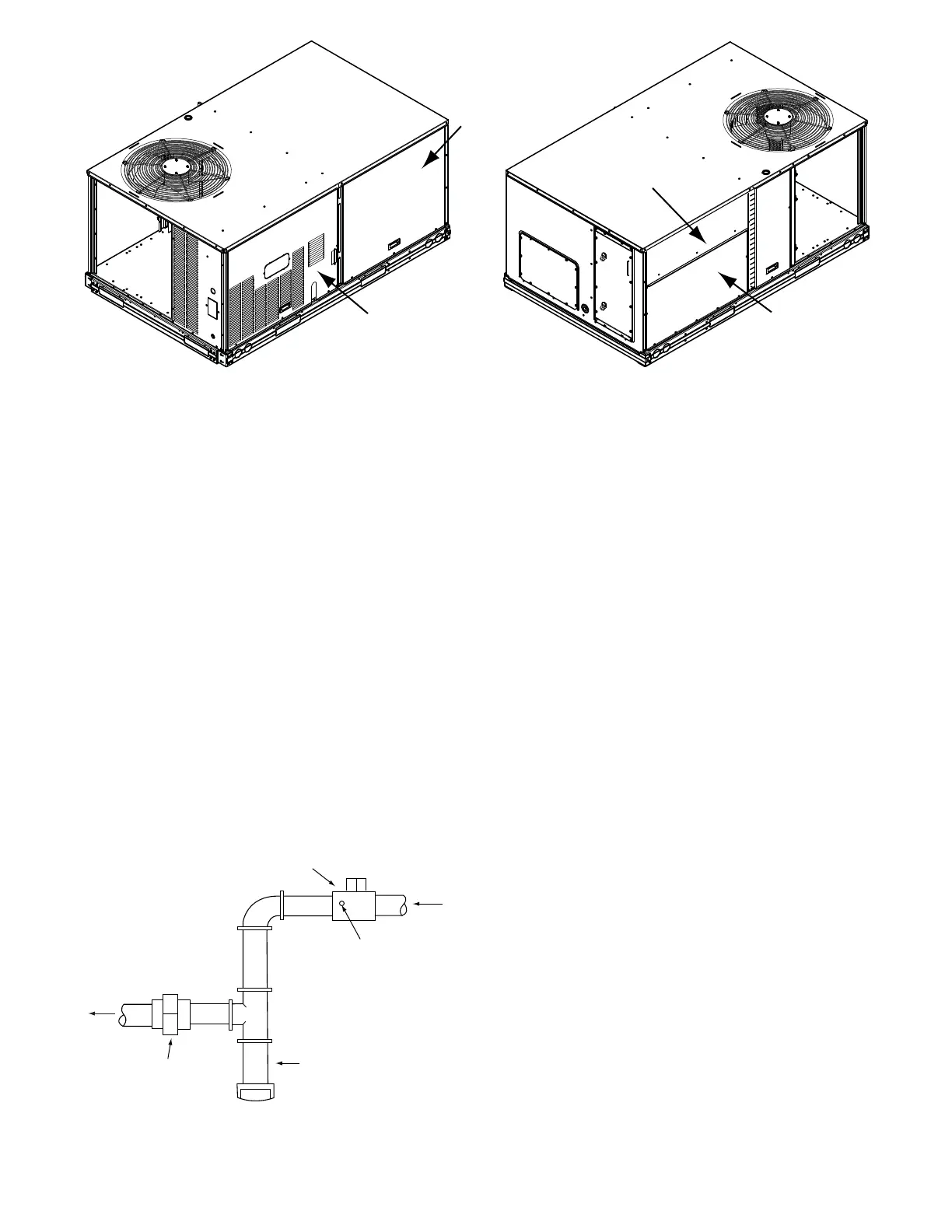
INDOOR
BLOWER
ACCESS
PANEL
CONTROL BOX
AND GAS SECTION
ACCESS PANEL
INDOOR COIL
ACCESS PANEL
FILTER
ACCESS PANEL
UNIT BACKUNIT FRONT
a48---9937
Fig. 6 -- Panel and Filter Locations
Return--Air Filters
Check that correct filters are installed in filter tracks (see Physical
Data table in unit Product Data). Do not operate unit without
return-air filters. Determine the filter change run time (DIRTY
FILTER TIME) to be set in the quick setup configurations menu.
Outdoor--Air Inlet Screens
Outdoor-air inlet screens must be in place before operating unit.
Accessory Installation
Check to make sure that all accessories including space thermostats
and sensors have been installed and wired as required by the
instructions and unit wiring diagrams.
Gas Heat (48FC and 48GC)
Inspect the gas heat section of the unit. Verify the number of
burners match the number of heat exchanger openings and the
burner assembly is properly aligned. If the orifices were changed
out for elevation or Liquid Propane purposes, verify proper
installation. Visually inspect other components in heat section.
Verify gas pressures before turning on heat as follows:
1. Close the field-supplied manual gas shut off valve, located
external to the unit.
2. Connec t a pressure gauge to the supply gas pressure tap,
located on the fi eld-supplie d ma nual ga s shut off valve (see
Fig. 7).
MANUAL GAS SHUT OFF VALVE
(FIELD SUPPLIED)
SUPPLY GAS
PRESSURE TAP
(1/8˝ NPT PLUG)
GAS
SUPPL
SEDIMENT TRAP
UNION
TO
UNIT
a48---9382
Fig. 7 -- Field Gas Piping
3. Connect a pressure gauge to the manifold pressure tap on
the burner assembly located inside the unit.
4. Open the field-supplied manual gas shut of f valve. Ente r
Service T est mode by setting TEST MODE to “ON” using the
SystemVut controller interface. Use the Service T est feature
to set HEAT 1 TEST to ON (f irst st age of hea t) us i ng the
SystemVu controller interface.
5. After the unit has run for several minutes, verify the supply
gas pressure is adequate per the base unit installation in-
structions. If not, adjust accordingly.
NOTE: Supply gas pressure must not exceed 13.0--in. wg.
6. Set HEAT 1 TEST to OFF using the SystemVu controller
interface.
7. Exit Service Test mode by setting TEST MODE to “OFF”
using the SystemVu controller interface.
CONTROLS QUICK SET--UP
The following information will provide a quick guide to setting up
and configuring t he 48/50FC and 48/50GC se ries units with
SystemVu controls. Unit controls are pre-configured at the factor y for
factory-installed options. Field-installed accessories will require
configuration at start-up. Initial System Startup is recommended for
initial start--up. Additionally, specific job requirements may require
changes to def ault c onfigura tion va l ues. See Appe ndix A and other
sections of these ins tructions f or more de t ails. Re fer to the Ma j or
System Component s or accessory installation instructions for specific
wiring detail.
Control Set Point and Configuration Log
During start up, accessory installation, and equipment service set
points and/or configuration changes might have to be made. When
setting set points or configuration settings, documentation is
recommend. The Control Set Point and Configuration Log starting
on page 132 should be filled out and left with the unit at all times,
a copy should also be provided to the equipment owner. A USB
jump drive can be used to back up the unit’s configurations. Refer
to the USB Operation section for details.
Initial Startup
Initial Startup refers to the first time this particular unit has a startup
performed. The SystemVu controller will continually display the
Initial Startup prompt until it is completed. To complete the initial
startup you must complete the Quick Setup, Network Setup, and
the System Auto Test.

 Loading...


