34
Control Module Communication
Red LED
Proper operation of the MBB control board can be visually
checked by looking at the red status LED. When operating
correctly, the red status LED should blink at a rate of once every 2
seconds. If the red LED is not blinking, verify that correct power is
being supplied. A blinking red LED at the rate of once per second
means that software is not loaded on the board. Also, be sure that
the board is supplied with the current software. If necessary, reload
current software. A board LED that is lit continuously should be
replaced.
Green LED
The MBB has one green LED. The Local Equipment Network
(LEN) LED should always be blinking whenever power is on. If
LEN LED is not blinking, check LEN connections for potential
communication errors (MBB J15, J16, J17, and on the Display J2).
Communication between modules is accomplished by a 3--wire
sensor bus. These 3 wires run in parallel from module to module.
The MBB J17 and Display J2 connectors provide both power and
communication directly at the connector for accessories like the
Navigatort display. The MBB J15 connector provides a LEN
interface to the indoor fan VFD.
Yellow LED
The MBB has one yellow LED which is used to indicate Building
Automated System (BAS) communication activity. The LED will
blink when the MBB transmits a message on the bus.
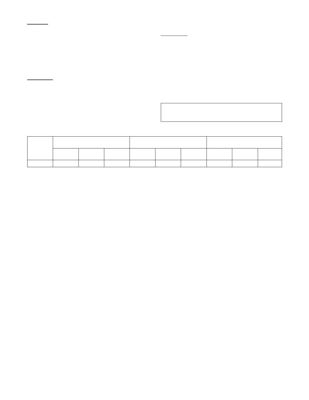
Communication Failures
If the Indoor Fan VFD or Navigator display Communication
Failure or the green or yellow LED’s do not flash on the boards
then the problem could be the communication chip on one of the
control boards (MBB). Use an ohm meter to measure the resistance
on the communication pins of the boards to determine if the board
is bad. If the reading is less then half the value indicated in Table
13, then the board needs to be replaced.
IMPORTANT: The resistive values should be read when the
board is powered off, the unit is locked out, and board
connectors are disconnected.
Table 13 – Communication Resistances
Device
(LEN) Resistance between Pins /
Connector
(BAS) Resistance between Pins /
Connector
(RNET) Resistance between Pins /
Connector
Pins
1to3
Pins
1to2
Pins
2to3
Pins
1to3
Pins
1to2
Pins
2to3
Pins
GND to +
Pins
GND to –
Pins
+to–
MBB 19.92 KΩ 10.63 KΩ 9.51 KΩ 19.92 KΩ 10.63 KΩ 9.51 KΩ 2.25 KΩ 1KΩ 3.3 KΩ

 Loading...


