EN
2 - COMPONENTS
The CCU CONTROLLER comprises:
2.1 - On the front:
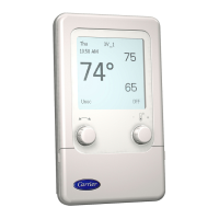
- A human-machine interface used to carry out adjustments, and signal and display the various states and information
- The display appears on a backlit LCD (4 lines x 40 characters).
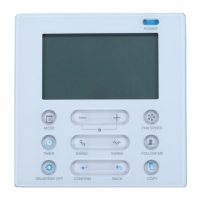
DESCRIPTION OF THE FRONT PANEL:
1 - Starting up (green LED)
2 - "Power on" indicator (yellow LED)
3 - Fault signal indicator (red LED)
4 - Reset
5 - Cursor pad
6 - Number pad
7 - Validation
8 - Correction
9 - Setpoints values
10 - 160-character LCD screen
The dialogue between the machines and the user is provided by simple, precise text messages on a 160-character LCD screen. The
CCU CONTROLLER automatically displays information on the operation of the unit.
(ExampleAppearance of a fault).
It comprises:
- A backlit crystal screen with 4 lines of 40 characters.
- A forced off or on authorisation push button, equipped with LED indication (green LED).
• Green LED off → unit off.
• Green LED ashing → remote control open.
• Green LED permanently on → unit on
- A voltage on indicator (yellow LED).
- A fault signal indicator (red LED).
- A "RESET" push button for resetting the faults.
- An "ENTER" push button to conrm (modication of a value).
- A push button "C" to delete the last digit displayed when modifying values.
- A push button "T" to quickly modify the setpoints for the unit being queried "heating, cooling, humidication, dehumidication" or
to quickly modify the trigger setpoint for the extra unit.
- A cursor pad.
- A number pad.
The user can congure or query the machines at any time via a tree menu, the rst window for which comprises the following sections
M O N 1 0 / 0 4 / 2 0 1 7 0 9 : 3 0 C C U C . S Y S T E M
C O N F I G U R A T I O N O F N U M B E R O F U N I T S
U N I T 1 : I N A U T O M A T I C M O D E
U N I T 2 : S T O P P E D
3
2
1
4
10
5
7
8 9
6
43
 Loading...