EN
6 - CONFIGURING THE UNIT
6.1 - Unit parameters
6.1.1 - UNIT TYPE (sub-menu 3.1)
To limit the amount of different software required whilst meeting our customers' need for applications, the CCU CONTROLLER is
provided with a conguration system. It allows the composition of the unit to be congured, along with all the functions which must be
managed by the system
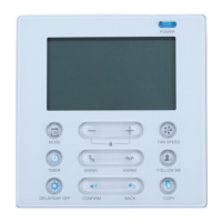
To congure the CCU CONTROLLER, use the menu No.3: PARAMETER and the sub-menu No. 3.1: UNIT TYPE. (Menu on CCU
CONTROLLER display)
These parameters are directly linked to the composition of the unit, and they must not be modied on site.
The procedure for saving these parameters is carried out in the workshop. (To view the type of programming specic to your control,
refer to the conguration guide attached to the unit).
To modify parameters P01 to P99, the unit must be stopped and the conguration unlocked. Parameter P99 (Locking of conguration)
is equipped with a system which counts the number of times the conguration is unlocked.
Most of the parameters can only be modied if the correct authorisation level is accessed in Menu No.8 of the CCU CONTROLLER
(See paragraph 4 in this guide).
Access level No. Description Setting By default Display condition
CONFIGURATION OF THE FANS
2 1 On control
1: Outer contact (the push button on the
console acts as a forced stop)
2: Internal timer (the push button on the
console acts as a priority forced stop and
the outer contact as a forced start)
1
3 2
Number of speeds or variation
of air ow rate
1: One speed
14
P05 = 0
10: Variation of the rotation speed with
increase of the speed via an increase in
cooling control.
P07 > 0
11: Variation of the rotation speed with
increase of the speed via an increase in
heating control.
P08 > 0
12: Variation of the rotation speed via
cooling and heating control.
P07 > 0 and P08 > 0
13: Variation of the rotation speed with
decrease of the speed via an increase in
dehumidication control.
P09 > 0
14: Manual variation of the fan rotation
speed.
15: Variation of the rotation speed with
pressure increase on the raised oor.
16: Variation of the rotation speed depending
on the temperature difference (return/supply
air)
17: Variation for constant ow rate control
P03 > 2 and P05 > 0'
3 3 Machine model
1: 50CJ conguration
2: 50CO conguration
1
3 5 FMA control
0: On/off or gradual 0-10 V
1: 1 MODBUS gradual FMA
2: 2 MODBUS gradual FMA
3: 3 MODBUS gradual FMA
0
CONTROL SELECTION
3 6
Limitation via the supply air
temperature
0: No limitation
0
P11 ≠ 0
1: With limitation
(Low limit affecting cooling control, high limit
affecting heating control)
3 7 Cooling control
0: No cooling control
01: One chilled water coil
2: One direct expansion system
3 8 Heating control
0: No heating control
0
1: One hot water coil
2: One electric heater
3: Electric heater or hot water coil via contact
53
 Loading...


