EN
12 - BUS FOR MASTER/SLAVE FUNCTION
12.1 - Bus connection
BETWEEN THE VARIOUS UNITS
12
33
213
321
ON
OFF
ON
OFF
ON
OFF
COM2
COM2
COM2
J9
J9
J9
Multiconductor cables shielded,
jacketed (shielding with
braiding), length between the 1st
and the last CCU CONTROLLER:
1000 m
1: Line A or +
2: Line B or -
3: Earth
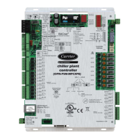
CCU CONTROLLER MASTER CCU CONTROLLER SLAVE
CCU CONTROLLER SLAVE
COM2: Bus polarisation switch
- Master unit = ON
- Slave unit = OFF
12.2 - Addressing procedure for the units
The rst time the power is switched on, all the boards are initialised with the parameter P215 "UNIT NUMBER ON CONSOLE" having
the value 1.
Connection diagram
Shunt to be removed from connector J2
Terminals 1 and 7
J9
Unit 1
Controller
CCU CONTROLLER
(P215 = 1)
J9
Unit 2
Controller
CCU CONTROLLER
(P215 = 2)
J9
Unit 3
Controller
CCU CONTROLLER
(P215 = 3)
On the controller for unit 1, in the "CONFIGURATION OF NUMBER OF UNITS" menu, "OPERATING CONFIGURATION", adjust the
parameter "C01 NUMBER OF UNITS": (3 in the example).
Addressing units
The parameter P215 must be set on each unit.
Position the cursor opposite unit 1 and press the "ENTER" key’.
In the "PARAMETERS"’, "SETTINGS PARAMETERS" menu, set parameter P215 to the value corresponding to the unit number.
69
 Loading...