SPT sensors
Carrier Sensors 7
4 Partially cut, then bend and pull off the outer jacket of the Rnet cable(s). Do not nick the inner insulation.
Strip about .25 inch (.6 cm) of the inner insulation from each wire.
Outer Jacket
Inner insulation
.25 in.
(.6 cm)
5 If wiring 1 cable to the SPT sensor, cut the shield wire off at the outer jacket, then wrap the cable with
tape at the outer jacket to cover the end of the shield wire.
If wiring 2 cables in a daisy-chain configuration, twist together the shield wires, then wrap the shield
wires with tape.
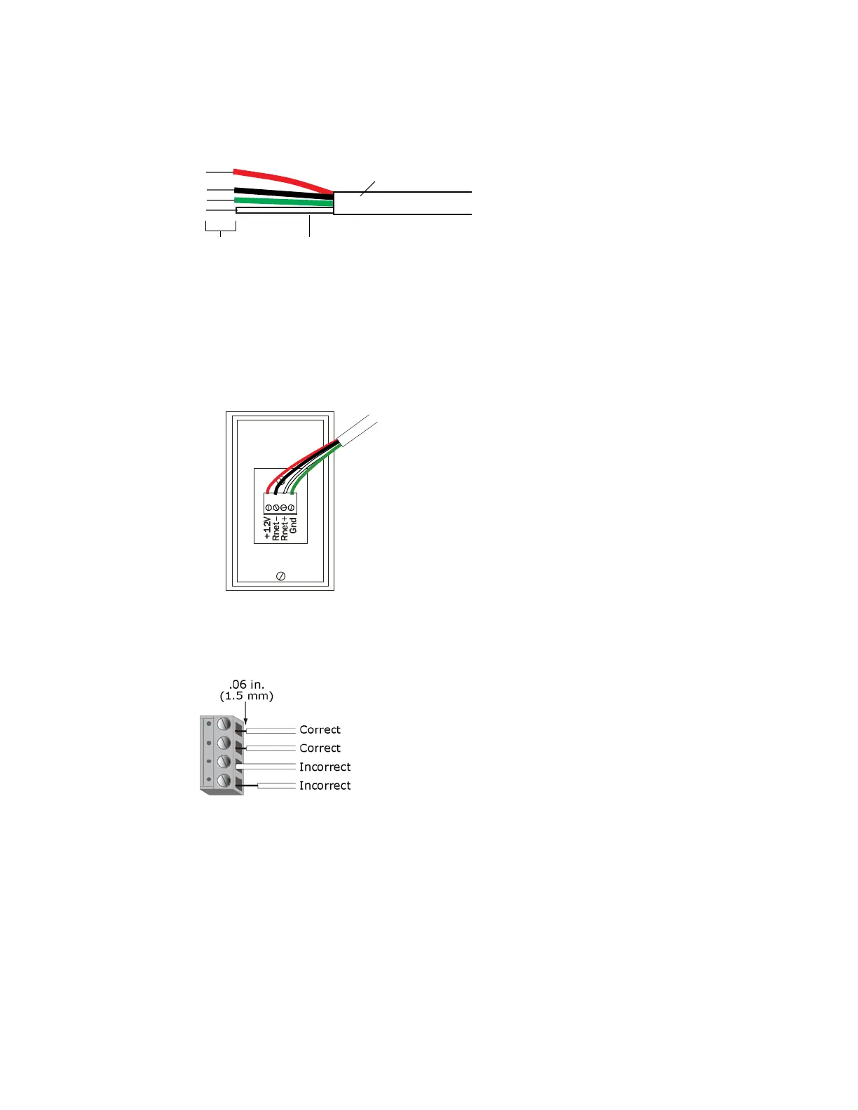
6 Insert the other 4 wires into the sensor's screw terminal connector. If wiring 2 cables, insert like-colored
wires into each terminal.
Carrier recommends that you use the
following Rnet wiring scheme:
Red
Black
White
Green
+12V
Rnet-
Rnet+
Gnd
CAUTION Allow no more than .06 inch (1.5 mm) bare communication wire to protrude. If bare
communication wire contacts the cable's foil shield, shield wire, or a metal surface other than the
terminal block, the sensor may not communicate correctly.
7 Attach the sensor's cover and circuit board to the mounting plate, inserting the top first.
8 Turn the setscrew one full turn counterclockwise to secure the cover to the mounting plate.
9 Wire the sensor to the Open controller. See the controller's Installation and Startup Guide for details.