SPT sensors
6 Carrier Sensors
Voltage 300 Vac, power limited
Listing UL: NEC CL2P, or better
Mounting location
Mount the sensor:
• In an area representing the average temperature in the space
• On an interior wall
• Approximately 5 feet (1.5 meters) from the floor, or as required by local code
• At least 4 feet (1.2 meters) from any corner
• At least 2 feet (.6 meter) from an open doorway
Do not mount the sensor:
• In drafty locations such as near air conditioning or heating ducts, or near open windows
• Over heat sources such as baseboard heaters, radiators, directly above wall-mounted lighting dimmers,
or in direct sunlight
NOTE The sensor mounting plate accommodates the NEMA standard 4x2-in. electrical box. However, the
sensor can be mounted directly on the wall surface if local codes permit.
To wire and mount the SPT sensor
NOTE The sensor mounting plate accommodates the NEMA standard 4x2-in. electrical box. However, the
sensor can be mounted directly on the wall surface if local codes permit.
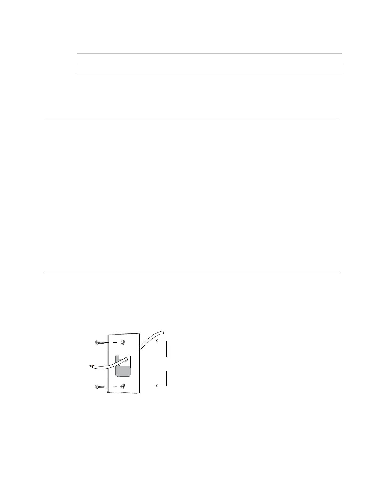
1 Remove the mounting plate from the SPT sensor. You may need to turn the setscrew in the bottom of the
sensor clockwise until you can remove the mounting plate.
2 Pull the Rnet communication cable through the wire guide in the mounting plate.
3 Use the 2 mounting screws provided to attach the mounting plate to the wall or electrical box.