Relative Humidity sensors
40 Carrier Sensors
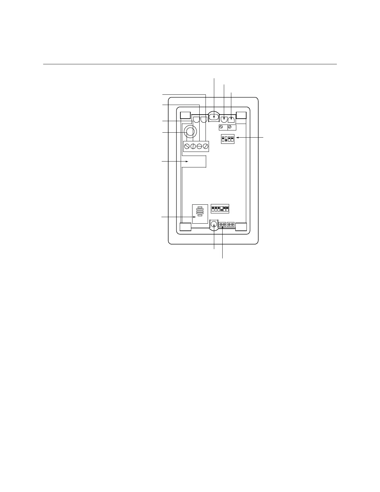
To wire and mount the Space RH sensors
Zero
VoGnd
VinIo
Span
SW2
S1 S2
Mounting hole
Zero adjust potentiometer
Span adjust potentiometer
Output selection
(#OPNSENSRH-01 only)
Mounting hole
Relative humidity temperature sensor
Wire access hole
Vdc or 24 Vac supply voltage
4–20mA output to controller
Vdc output to controller
Ground or signal common (for
voltage output transmitters only)
Relative humidity sensor
1 2 3 4 5 6
ON
SW3
1 2 3 4
ON
1 Remove the sensor's cover from the mounting plate.
2 Feed the wires from the electrical box through the wire access hole in the center of the sensor mounting
plate.
3 Use the 2 screws provided to attach the mounting plate to the electrical box.
4 Strip the outer jacket from the cable for at least 4 inches (10.2 cm). Strip .25 inch (.6 cm) of insulation
from each wire.
5 Wire the unit for power. See Typical power wiring diagrams for Space RH sensors (page 42).