Enthalpy switch/receiver and Enthalpy sensor
52 Carrier Sensors
4 Set the M1 to M3 jumper to M2. Leave the other jumper on Off.
NOTE The enthalpy sensor's jumpers should be left at their factory settings of M3 and Off.
5 Replace the switch/receiver's cover and the 4 screws.
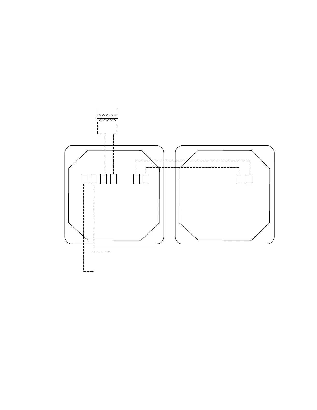
6 Wire the sensor to the switch/receiver. See figure below.
7 Connect the GND and 24 Vac terminals on the enthalpy switch/receiver to the controller's power
terminals.
8 Connect the HI or LOW terminals on the enthalpy switch/receiver to the controller's J2-6 input.
33CSENTHSW
24 Vac
secondary
HI LOW GND 24
ENTHALPY VAC
4-20 24-36
mA VDC
IN OUT
24-36 4-20
VDC mA
IN OUT
120 Vac
line
voltage
33CSENTSEN
24 Vac output from n/c contact when the outdoor
enthalpy is less than the indoor enthalpy
(Enable economizer)
24 Vac output from n/o contact when the indoor
enthalpy is greater than the outdoor enthalpy
(Enable energy recycler)