Installing the Zone Ctrl II
Zone Ctrl II and
VAV Zone II Secondary Duct Installation and Start-up Guide CARRIER CORPORATION ©2019
Error! No text of specified style in document.
18 All rights reserved
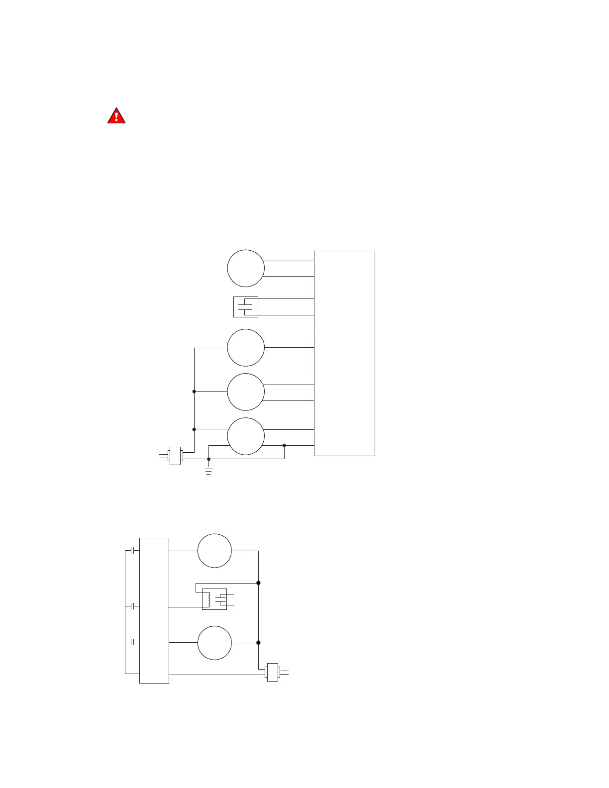
To wire inputs and outputs
Do not apply line voltage (mains voltage) to the controller's ports and terminals.
1 Verify that the Zone Ctrl II's power and communications connections work properly.
2 Pull the screw terminal connector from the controller's power terminals labeled
and
.
3 Connect the input wiring to the screw terminals on the Zone Ctrl II.
○ Connect the shield wire to the
terminal with the ground wire.
○
and
share the
terminal beside
.
Dry
contact
Any input
Any input
Gnd
IN
Gnd
IN
Gnd
IN-1 or IN-2 only
Gnd
IN-1 or IN-2 only
Gnd
IN-1 or IN-2 only
Thermistor
24 Vdc
half-wave
power
supply
2 wire
3 wire
4 wire
Out
V+
Gnd
Out
V+
n/c
Out +
Out -
V+
Gnd
0-5 Vdc
0-5 Vdc
0-5 Vdc
4 To use
or
, set jumpers
or
to the type of signal the input will receive (thermistor/dry
contact, or 0–5 Vdc).
5 Connect the binary output wiring to the screw terminals on the Zone Ctrl II and to the controlled device.
24 Vac
Motor
Valve
Any BO
An
y BO
Bus
Any BO