Installing the Zone Ctrl II
Zone Ctrl II and
VAV Zone II Secondary Duct Installation and Start-up Guide CARRIER CORPORATION ©2019
Error! No text of specified style in document.
21 All rights reserved
To wire the Wireless Adapter for wireless sensors
Do not apply line voltage (mains voltage) to the Wireless Adapter.
The Carrier wireless sensors are available in 868, 902, and 928 MHz radio frequency. The sensors are thermistor-
based temperature sensors that may optionally sense humidity.
Wireless sensors communicate through a Wireless Adapter, which is wired to the Rnet port of the controller.
• A v6.5 or later i-Vu® system
• v6-xx-xxx or later controller drivers
To configure the control program for the desired user interaction with the sensor, see the Wireless Sensors
Application Guide. For detailed instructions, see the Wireless Sensors Installation Guide.
To wire, power, and mount the Wireless Adapter
• The Wireless Adapter requires a 24 Vac power supply. It is not powered by the Rnet.
• If the Wireless Adapter will be:
○ Daisy-chained on the Rnet with ZS sensors, an Equipment Touch, or TruVu™ ET Displayuse the standard
4-conductor Rnet wiring.
○ The only device on the Rnet, you can use a 3-conductor cable instead of the standard 4-conductor Rnet
cable.
1 Turn off the power to the controller that the Wireless Adapter will be wired to.
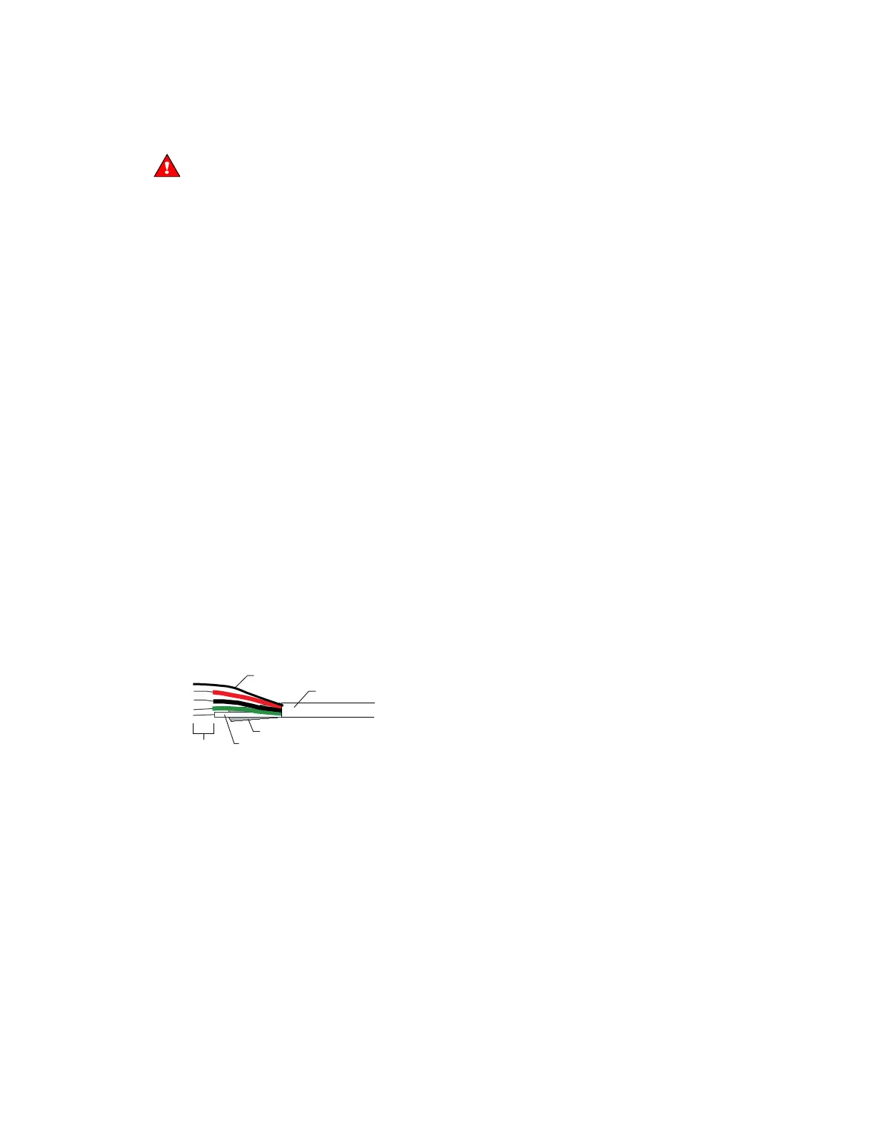
2 Partially cut, then bend and pull off the outer jacket of the Rnet cable(s). Do not nick the inner insulation.
Inner insulation
Outer jacket
Foil shield
.25 in.
(.6 cm)
Shield wire
3 Strip about 0.25 inch (0.6 cm) of the inner insulation from each wire.