Overview and specifications
Zone Ctrl II and
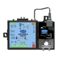
VAV Zone II Secondary Duct Installation and Start-up Guide CARRIER CORPORATION ©2019
Error! No text of specified style in document.
4 All rights reserved
Memory 512 kB non-volatile battery-backed RAM, 1 MB Flash memory, 16-bit memory bus
Battery 10-year Lithium CR2032 battery retains the following data for a maximum of
10,000 hours during power outages: control programs, editable properties,
schedules, and trends.
Protection Built-in surge and transient protection for power and communications in
compliance with EN61000-6-1.
Incoming power and network connections are protected by non-replaceable
internal solid-state polyswitches that reset themselves when the condition that
causes a fault returns to normal.
The power, network, input, and output connections are also protected against
transient excess voltage/surge events lasting no more than 10 msec.
To protect against large electrical surges on serial EIA-485
networks, place a PROT485 at each place wire enters or exits the building.
BT485 connector You attach a BT485 (not included) to a controller at the beginning and end of a
network segment to add bias and to terminate a network segment.
Status indicators LEDs indicate status of communications, running, errors, power, and binary
outputs
Environmental operating
range
32 to 130°F (0 to 54.4°C), 10–90% relative humidity, non-condensing
Storage temperature range -24 to 140°F (-30 to 60°C), 0 to 90% relative humidity, non-condensing
Physical UL94-5VA plenum rated enclosure for installation in plenum (or other space for
environmental air) in accordance with NEC Section 300.22 (c) and (d)
Controller and actuator
overall dimensions
Width:
Height:
8.9 in. (22.7 cm)
5.9 in. (15.0 cm)
Controller and actuator
mounting dimensions
7.1 in. (18.0 cm) from left side controller mounting hole centerline to actuator
mounting hole centerline
Controller overall
dimensions
Width:
Height:
Depth:
6.4 in. (16.3 cm)
5.7 in. (14.5 cm)
2.1 in. (5.3 cm)
Controller mounting
dimensions
5.3 in. (13.4 cm) from left side controller mounting hole centerline to right side
controller mounting hole centerline
Actuator overall dimensions Width:
Height:
Depth:
3.0 in. (7.6 cm)
5.9 in. (15.0 cm)
2.5 in. (6.4 cm)
Actuator mounting
dimensions
4.4 in. (11.2 cm) from shaft centerline to actuator mounting hole centerline
Weight 1.8 lbs (0.82 kg)
BACnet support Conforms to the BACnet Advanced Application Controller (B-AAC) Standard Device
Profile as defined in ANSI/ASHRAE Standard 135-2012 (BACnet) Annex L, Protocol
Revision 9
Listed by UL-916 (PAZX), cUL-916 (PAZX7), FCC Part 15-Subpart B, Class B, CE