DISTRIBUTION SYSTEMS - HIGH-FLOW HYDRAULIC POWER SYSTEM
Control valve - Remove (A.16.A.14 - F.10.A.10)
435, 445, 445CT
1. Remove the cap from the hydraulic reservoir and
install the CAS 1871 adapter on the reservoir.
2. Connect the CAS10192 vacuum pump to the
adapter. Reservoir - Apply vacuum (A.10.A.22 -
F.35.A .50)
3. Start the vacuum pump.
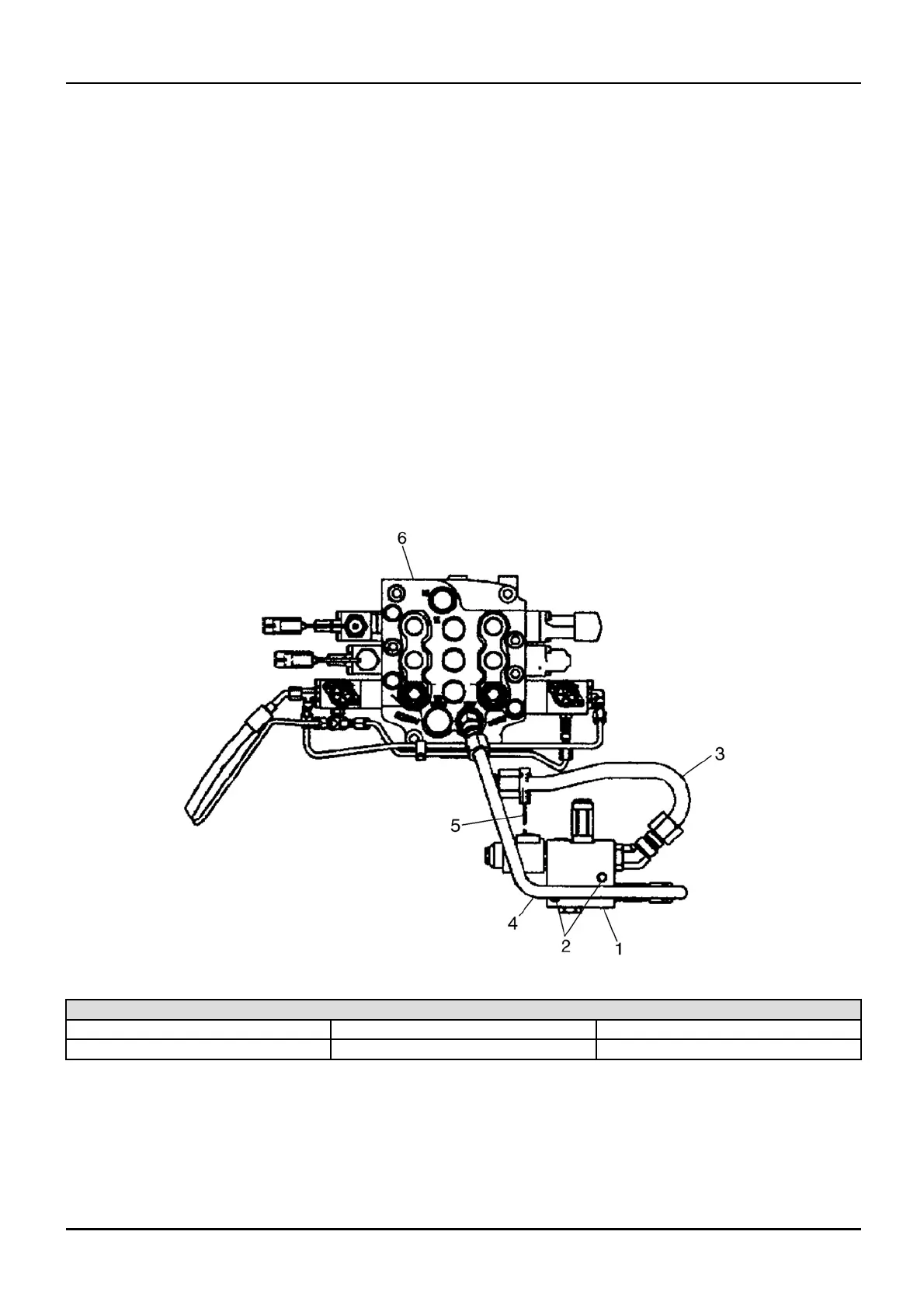
4. Loosen and remove the hydraulic lines (3) an d (4)
from the control valve (1).
5. Place caps on the fittings and plugs in the lines.
6. Stop the vacuum pump.
7. Disconnect the electrical harness (5) from the
control valve electrical connector.
8. Loosen and remove the mounting bolts(2) from the
control valv e (1).
9. Remove the control valve (1) from the machine.
bs04d135 1
High-Flow Control Valve
1. High-Flow Control Valve
3. Hydraulic Line Electrical Harness
2. Mounting Bolts 4. Hydraulic Line
6. Loader Control Valve
1 04/05/2005
A.16.A / 11