Hardware Setup 2-3
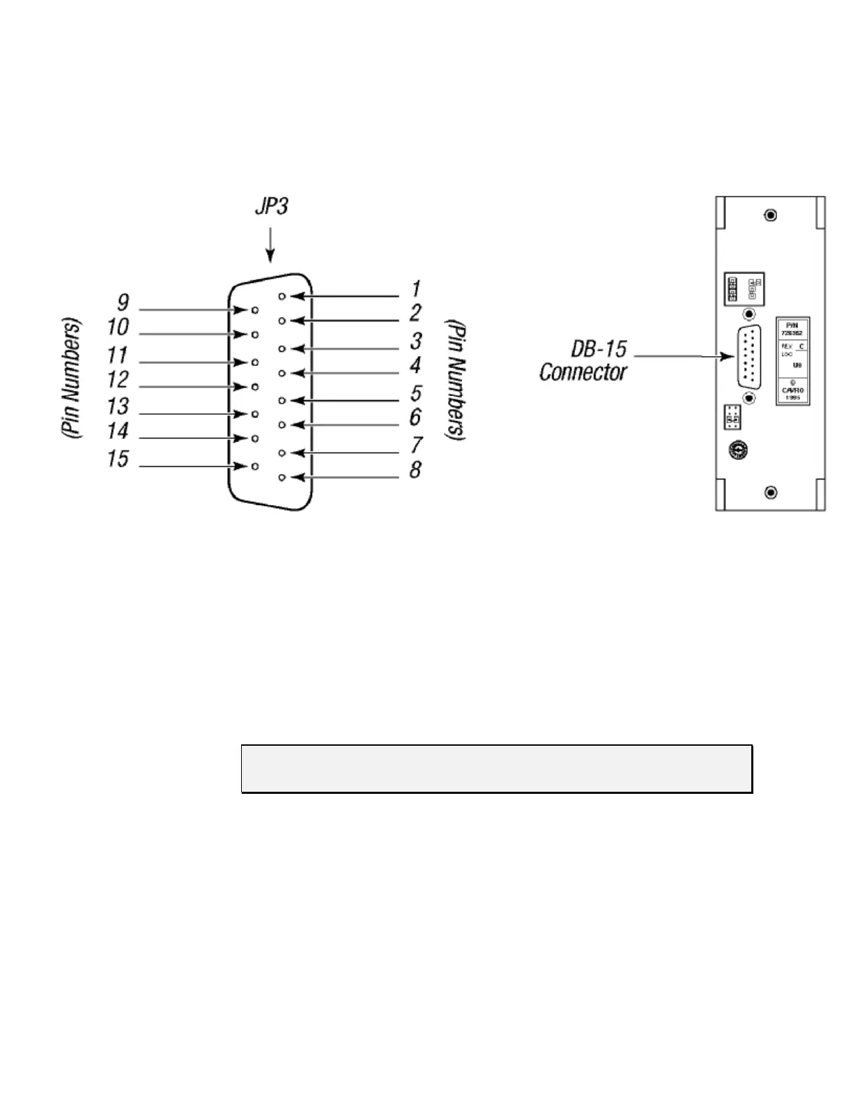
Figure 2-1 shows the pin positions of the DB-15 connector on the printed circuit board.
This is a male connector that requires a female connector on the mating cable.
Figure 2-1. DB-15 Connector Pins
Communication Interfaces
The computer or controller communicates with the XP 3000 through an RS-485 interface,
RS-232 interface, or CAN (Controller Area Network) interface. The RS-232 interface
automatically converts the protocol to RS-485 for the benefit of any other devices which
may be connected to the XP 3000’s RS-485 communications bus (this constitutes a so
called “multi-drop” device configuration).
NOTE The RS-232 interface does not support hardware handshaking and requires
only three lines: RXD, TXD, and Signal Ground.
When using a multi-drop arrangement, up to 15 pumps can be addressed by the controller
on the same communications bus (up to 16 pumps for microstep-enabled firmware). Take
special care to ensure that the RS-485 A and B lines are not reversed. Special
consideration must be given to the position of jumpers on JP2. These jumpers switch
termination resistors into the RS-485 A and B line circuits, thereby dampening the signal
at the ends of the RS-485 chain. This prevents echoing of the signal back to the listeners
on the chain. Multi-drop configurations require jumpers in both positions of JP2 for the
first and last pump in the RS-485 chain (i.e., the ends of the chain). Single pump
configurations (i.e., only one pump communicating with a controller) always require that
jumpers be installed on JP2.