Software Communication 3-12
CAN Interface Communications
CAN (Controller Area Network) is a two-wire, serial communication bus. It eliminates
polling sequences that verify task completion. Using CAN, the pumps asynchronously
report to the master or host when they have finished the current task.
NOTE All Cavro XP 3000s use CAN controller chip compatible with Philips
Semiconductor CAN bus specification, version 2.0.
CAN MESSAGES
CAN messages consist of frames. Each frame has an 11-bit Message Identifier (MID).
The bits:
indicate to which device on the bus the message is directed
identify the message type
show the direction of the message (to or from the master device)
represent the length of the data block. Data blocks can be from zero to eight bytes
in length. Any message that requires more than eight bytes must be sent in a series
of multi-frame messages. The receiving unit then assembles the separate frames
into one long string.
CAN MESSAGE CONSTRUCTION
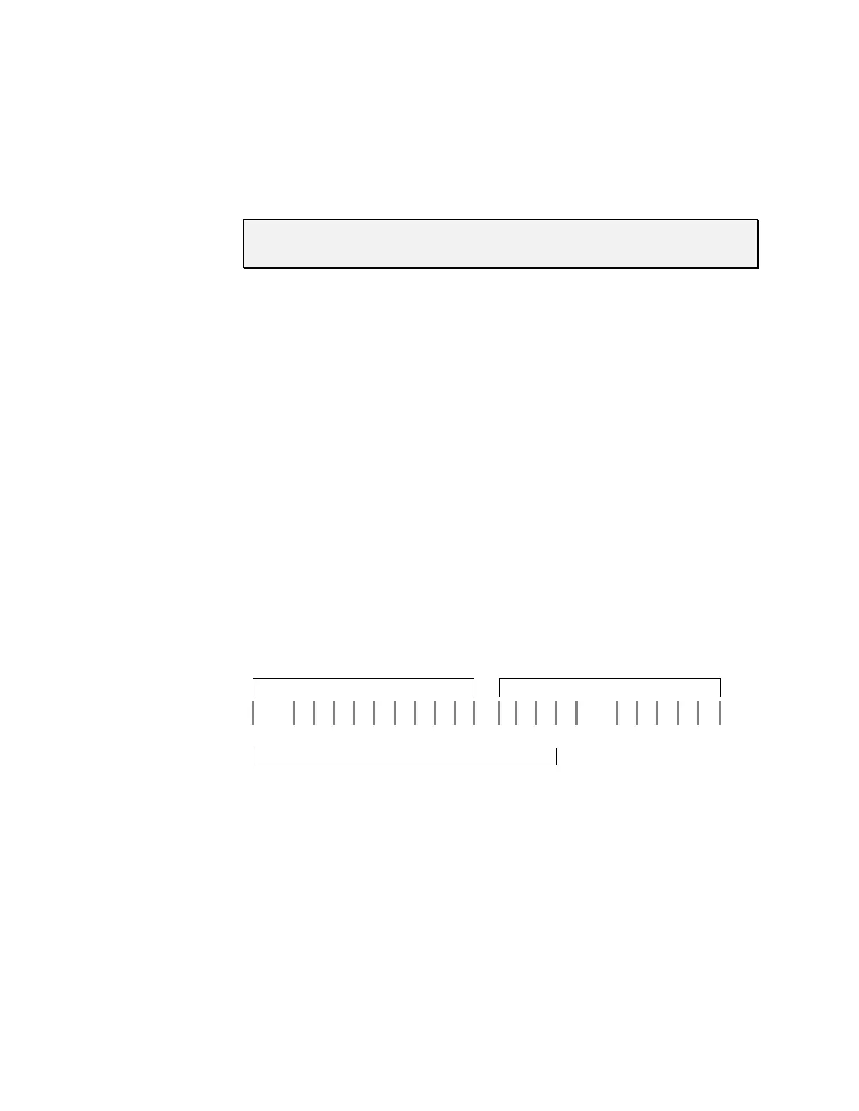
Each message frame begins with the MID. The data block (up to 8 bytes in length)
follows the MID and length information. This information makes up two bytes that are
transmitted first in a message frame. Their bits are grouped as shown:
Byte 1 Byte 2
0/1 210 3210 210 0/1 3210
Dir Group Device Frame RTR Length
11 Bit MID
Dir
This is the direction bit. It lets the devices on the bus know whether the current
message is to or from the master. “0” means that the message is from master to
slave; “1” means the message is from the slave to the master.
Group
This is the group number (0 - 7). Each type device on the XP 3000 CAN has a
group assignment. The XP 3000 is assigned to group 2. The group number “1” is
reserved for the boot request procedure.