Contents vi
Set Commands.......................................................................................................2
Microstep-Enabled Firmware Commands..............................................................3
Report Commands .................................................................................................3
Error Codes ............................................................................................................3
Error Codes and Status Byte..................................................................................4
DB-15 Connector Pin Assignments........................................................................4
Figures
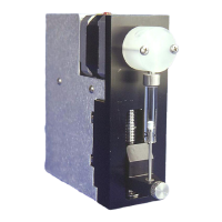
Figure 1-1. XP 3000 Modular Digital Pump.............................................................................................. 1-3
Figure 1-2. Syringe Components ............................................................................................................. 1-4
Figure 1-3. 3-Port Valve Components...................................................................................................... 1-5
Figure 1-4. XP 3000 Printed Circuit Board External Connectors .............................................................. 1-6
Figure 2-1. DB-15 Connector Pins ........................................................................................................... 2-3
Figure 2-2. Termination Jumpers ............................................................................................................. 2-4
Figure 2-3. RS-232 Multi-Pump Cabling .................................................................................................. 2-5
Figure 2-4. RS-485 Multi-Pump Cabling ................................................................................................... 2-6
Figure 2-5. CAN Multi-Pump Cabling........................................................................................................ 2-7
Figure 2-6. Configuration Jumpers........................................................................................................... 2-8
Figure 2-7. JP4 Jumper Settings Per Mode........................................................................................... 2-10
Figure 2-8. Printed Circuit Board Settings for Microstep-Enabled Firmware ......................................... 2-12
Figure 2-9. Address Switch .................................................................................................................... 2-13
Figure 2-10. XP 3000 Valve Installation (3-Port Valve Shown).............................................................. 2-16
Figure 2-11. Syringe Installation............................................................................................................. 2-18
Figure 2-12. XP 3000 Threaded Mount Holes........................................................................................ 2-20
Figure 3-1. Valve Positions for all Valve Types...................................................................................... 3-32
Figure 4-1. Syringe Speed........................................................................................................................ 4-2
Figure 5-1. Syringe Replacement............................................................................................................. 5-5
Figure 5-2. Syringe Seal Assembly.......................................................................................................... 5-6
Figure 5-3. XP 3000 Valve Replacement (3-Port Valve Shown).............................................................. 5-7
Figure B-1. Plunger Force Curve .................................................................................................................1