page 37 www.centsys.com
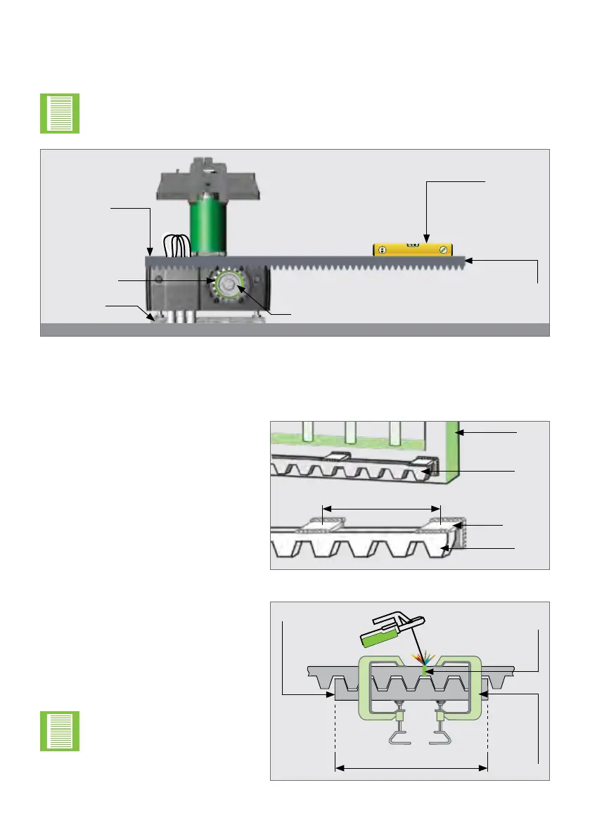
Pinion Spyder
First
Secured End
Spirit Level
Pinion
Foundation
Plate
FIGURE 56. THE RACK AND OPERATOR FROM THE GATE'S PERSPECTIVE
Slidethegatehalfwayalongtherstsectionandleveltheunsecuredend,ensuringthat
therackisrestingonthePinionSpyder,notpressingdown.Continuethiswaytoxall
sections.
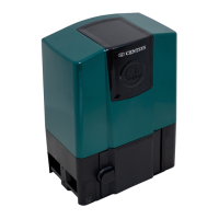
Level this end of the rack,
and x it to the gate
Beforefullyxingeachsectionofrack,slidethegatebackwardsandforwards
along the section, checking that the rack is only resting on the Pinion Spyder,
and not pressing down onto it.
OPERATOR INSTALLATIONSECTION 7
7.9.1. Fitting Dierent Types of Rack to the Gate
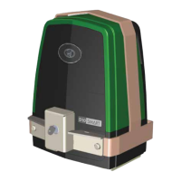
Steel Rack
FIGURE 57
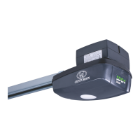
FIGURE 58
±300mm
Gate
Steel
Rack
Welded
join
Clamp
O-cut
Steel
Bracket
Steel
Rack
Fix the Steel Rack with the steel
angle brackets provided. The
brackets must be spaced no more
than 300mm apart.
Whenjoiningdierentlengthsof
Steel Rack, a simple way of ensuring
that the correct pitch spacing is
achieved,istoclampasmallo-cut
between the two pieces.
Donotweldtheo-cut
to the gate or the join.
±300mm