24
Entrapment Protection
Monitored Entrapment
Protection
IMPORTANT INFORMATION ABOUT THE
MONITORED ENTRAPMENT PROTECTION
DEVICES
Eyes/ Edge inputs will not be functional until the
system is commissioned / programmed.
NOTE: LED on Eye / Edge will not illuminate.
A monitored entrapment protection device is
required for most operation modes (see "Monitored
Eyes/Edge Conguration" on page 30). If
a monitored entrapment protection device is
not installed, constant pressure to close will be
required from the wall controller.
See "Accessories" on page 63 for a complete list
of monitored entrapment protection devices.
Three EYE/EDGE terminals are provided. Each
terminal can accept ONE device. For easy
identication during installation, the correct
terminals are yellow.
NOTE: A set of photoelectric sensors (photo eyes) are included and must be installed, except for constant pressure
to close. Depending on your installation and usage needs, please consult with your installation specialist to see if the
addition of a contact edge sensor on the leading edge of the door, a cable tension monitor and/or a light curtain is also
needed.
WARNING
To prevent possible SERIOUS INJURY or DEATH from a
closing door:
• Be sure power is NOT connected to the door operator
BEFORE installing the photoelectric sensor(s).
• The door MUST be in the fully opened or closed
position BEFORE installing the LiftMaster Monitored
Entrapment Protection Device(s).
To prevent SERIOUS INJURY, DEATH, ENTRAPMENT, or
PROPERTY DAMAGE:
• Correctly connect and align the photoelectric sensor.
• Install the primary monitored photoelectric sensor
beam NO HIGHER than 6" (15 cm) above the oor.
• This is a required LMEP Device for B2, TS, T, and FSTS
wiring types and MUST NOT be disabled. For D1,
C2, and E2 wiring the installation of an entrapment
protection device is recommended.
• LiftMaster Monitored Entrapment Protection Devices
are for use with LiftMaster Commercial Door Operators
ONLY. Use with ANY other product voids the warranty.
• If an edge sensor is being used on a horizontal slide
door,place one or more edge sensors on both the
leading and trailing edge.
• If an edge sensor is being used on a vertical moving
door,place edge sensors on the bottom edge of the
door.
• NEVER try to loosen or remove an obstruction that
has impeded the movement of the door. Both the
obstruction and door are under EXTREME tension
and loosening or removing an obstacle, impeding the
movement of the door, can cause SERIOUS PERSONAL
INJURY.
• NEVER stand under a door that has been impeded by
an obstruction. KEEP CLEAR. Door could move freely at
any time and can cause SERIOUS PERSONAL INJURY.
• If the door should be obstructed or impeded in its
movement, ALWAYS call an Authorized Trained Service
Technician to clear that obstruction.
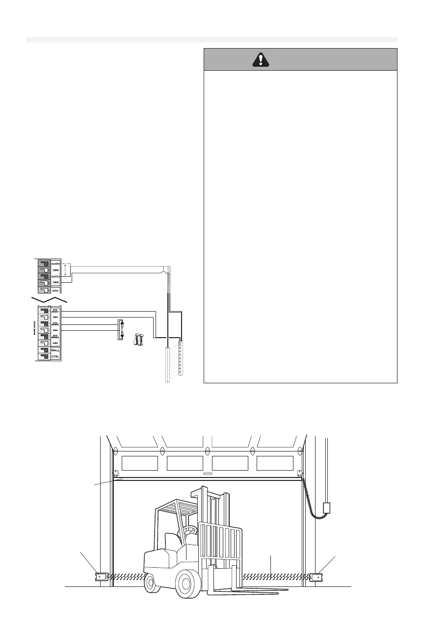
CPS-U, CPS-UN4,
CPS-OPEN4, OES-RD16
LC36M
Tx
Rx
LC36M
White/Black
To EYE/EDGE
To CMN
White
White
White/Black
Blue
Brown
Photo Eyes
Light Curtain
CLASS 2 SUPPLY +24V
ACCESSO RY POWER 24VDC, 1A
Blue
Brown
Accessories may connect to the regular or switched port.
Switched is turned off at loss of AC to preserve battery life.
Invisible Light Beam
Protection Area
Monitored Photoelectric
Sensor 6" (15 cm) max.
above the floor.
Monitored Edge Sensor
mounted to the bottom
of door.
Monitored Photoelectric
Sensor 6" (15 cm) max.
above the floor.
Typical Entrapment Protection Device(s) Overview