44
Auxiliary Relays Accessory Kit (AUXREL)
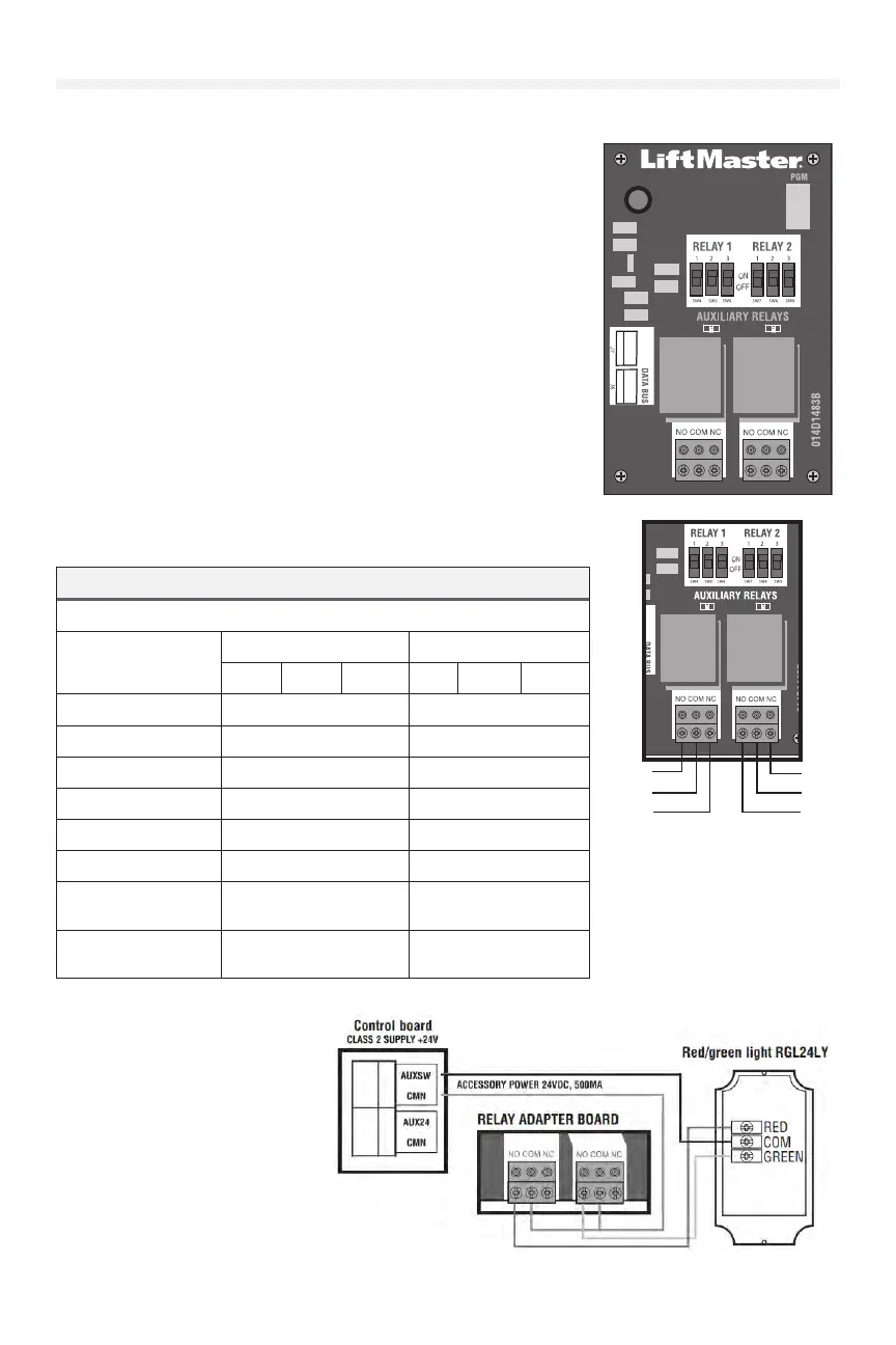
Congure the Relay Adapter
This operator allows for the programming of a single mid-stop door position.
To set the open mid-stop position:
1. In Programming Mode, go to Door Position => Open Mid-Stop or
Close Mid-Stop.
2. Use the Up/Down buttons to move the door to the desired position.
3. Select Save = Enter
To erase the mid-stop, select Erase Open Mid-Stop or Erase Close-Mid
Stop option, then select Save=Enter.
NOTE: Restoring defaults or resetting limits will erase the mid-stop position.
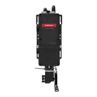
AUXILIARY RELAYS
• Aux Relay Switches: Set the AUX RELAY switches as needed to
obtain the desired function as shown below.
• J6 Input: Communicator bus connects control board, expansion
board, or relay adapter board.
• J7 Input: Communicator bus connects control board, expansion
board, or relay adapter board.
• AUX24: Supplies +24Vdc up to 1AMP to wired accessories.
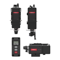
RED/GREEN LIGHT FUNCTIONALITY
Red light wired to AUX RELAY 1. Green light wired to AUX RELAY 2.
DOOR STATE AUX RELAY 1 SWITCHES AUX RELAY 2 SWITCHES
1 OFF 2 OFF 3 OFF 1 ON 2 ON 3 ON
Closed Red light OFF* Green light OFF
Opening Red light ON/Flash Green light OFF
Open Red light OFF Green light ON
Closing Red light ON/Flash Green light OFF
Dened Mid Stop N/A N/A
Undened Mid Stop Red light ON Green light OFF
Timer more than 5
seconds
Red light OFF Green light ON
Timer less than 5
seconds
Red light ON/Flash Green light OFF
* For red light ON when gate is closed, set switch 1 on AUX RELAY 1 to ON.
4.
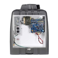
AUXILIARY RELAYS
The expansion board and relay adapter board provide Normally Open (N.O.) and Normally Closed (N.C.) relay contacts to control external devices, for
connection of Class 2, low voltage (42 Vdc [34 Vac] max 5 Amps) power sources only. Function of relay contact activation determined by switch settings.
AUX RELAY
SETTING
SWITCH SETTINGS
AUX RELAY 1 AUX RELAY 2
1 2 3
Off (no feature
selected)
OFF OFF OFF Relay always off. Use this Aux Relay setting to conserve battery power.
Open Limit Switch
OFF OFF ON Energizes at open limit. Use with SAMS (Sequenced Access Management System, jointly with barrier gate).
Close Limit Switch
OFF ON OFF Energizes when not at close limit. For an additional audible or visu al display, connect an external light (low voltage).
Gate Motion
OFF ON ON
Energizes when motor is on (gate in motion). For an additional audible or visual display, connect an external buzzer or light
(low
voltage).
Pre-Motion Delay -
Expansion Board Only
ON OFF OFF
Energizes 3 seconds before gat e motio n and remains energized
during gate motion. The onboard alarm will sound. For an
additional audible or visual display, connect an external buzzer or
light (low volt age).
En
ergizes 3 seconds before gate motion and remains energized
during gate motion. For an additional audib le or visual display,
connect an external buzzer or light (low voltage).
Power
ON ON OFF
Energizes when AC power or solar power is present. There is
approximately a 10-
12 second delay before relay cutoff, after AC
shutdown.
Energizes when on battery power.There is approximately a 10-12
second delay before relay cutoff, after AC shutdown.
Tamper
ON OFF ON
Energizes if gate is manually tampered with by being pushed off of close li
mit. For an additional audible or visual display, connect an
external buzzer or light (low voltage).
Cycle Count - Expansion
Board Only
ON ON ON
The 1, 2, and 3 LEDs will blink out the cycle count (cycle count is
stored on the control board). See below.
Red/green light functionality, see below.
N.O.
Com
N.C.
N.O.
Com
N.C.
RED/GREEN LIGHT FUNCTIONALITY
Red light wired to AUX RELAY 1 . Green light wired to AUX RELAY 2.
DOOR STATE
AUX RELAY 1 SWITCHES
AUX RELAY 2 SWITCHES
1 OFF 2 OFF 3 OFF 1 ON 2 ON 3 ON
Closed
Red light OFF* Green light OFF
Opening
Red light ON/Flash Green light OFF
Open
Red light OFF Green light ON
Closing
Red light ON/Flash Green light OFF
Defined Mid Stop
n/a n/a
Undefined Mid Stop
Red light ON Green light OFF
Timer more than 5
seconds
Red light OFF Green light ON
Timer less than 5
seconds
Red light ON/Flash Green light OFF
* For red light ON when gate is closed, set switch 1 on AUX to ON
RELAY ADAPTER BOARD