22
Wiring
WARNING
To prevent possible SERIOUS INJURY or DEATH:
• ANY maintenance to the operator or in the area near the operator MUST NOT be performed until disconnecting
the electrical power and locking-out the power. Upon completion of maintenance the area MUST be cleared and
secured, at that time the unit may be returned to service.
• Disconnect power at the fuse box BEFORE proceeding. Operator MUST be properly grounded and connected in
accordance with national and local electrical codes. The operator should be on a separate fused line of adequate
capacity.
• ALL electrical connections MUST be made by a qualied individual.
• DO NOT install ANY wiring or attempt to run the operator without consulting the wiring diagram.
• ALL power wiring should be on a dedicated circuit and well protected. The location of the power disconnect
should be visible and clearly labeled.
• ALL power and control wiring MUST be run in separately.
Power and Ground
Power and control wiring must be run in separate conduit to comply with national and local electrical codes. For power
wiring, use the appropriate wire gauge. Use conduit knockouts, conduit ttings, and appropriate conduit ttings for
wiring as indicated on the electrical box label.
1. Open the operator cover.
2. Run power wires to electrical box according to
national and local electrical codes.
NOTE: ON THREE PHASE POWER only use two of the
power legs cap o the third leg.
3. Attach power and ground wires to appropriate
terminals. Incoming power leads go to L1 and L2.
Ground is on the EMI lter board.
NOTE: The operator must be properly grounded.
Failure to properly ground the operator could result in
electric shock and serious injury.
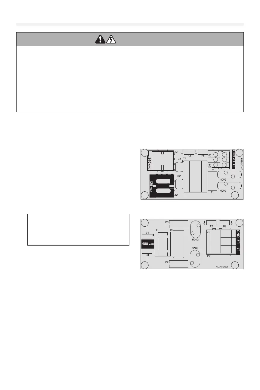
Voltage Selection
NOTE: LiftMaster oers two types of EMI lter boards.
However, each operator will ONLY house a single type
of board, dependent on operator voltage specication
ordered. Reference Image A for 120/ 240Vac and Image B for 480Vac.
1. Locate EMI lter board inside of the electrical box.
2. Remove the Orange voltage sticker covering the voltage connector/s and stick it to the inside of the electrical box.
3. On units with type (A) EMI lter board. Verify incoming voltage and phase1 or phase3 type.
4. Plug the connector to the appropriate plugin labeled 120Vac OR 240Vac.
Image A
Image B
* Maximum wire gauge that can be connected to
the operator’s terminal is 12 AWG. When a larger
wire gauge is required, the wire must be gauged
down to 12 AWG. USE COPPER WIRE ONLY.