CHANGHE FREEDOM SERVICE MANUAL ELECTRICAL SYSTEM
FUEL SENDER GAUGE INSPECTION
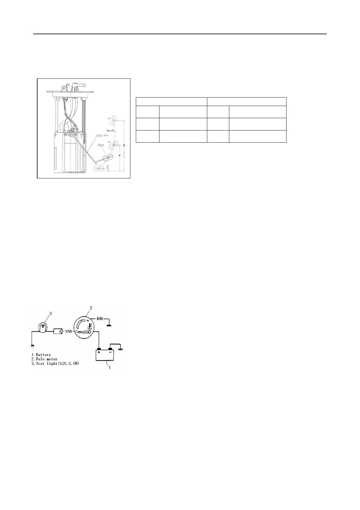
Remove fuel pump assembly referring to Section 6C of this
manual.
Use an ohmmeter to confirm that resistance of sender gauge
unit changes with change of float position.
Float Position
Resistance(Ω)
0 E 110
a 80.5mm 1/2 32.5
b 157mm F 3
If the measured value is out of specification, replace.
ENGINE COOLANT TEMPERATURE METER AND
SENSOR UNIT
DESCRIPTION OF CIRCUIT
The coolant temperature gauge circuit consists of coolant
temperature meter installed in the cluster and the coolant
temperature sensor unit on the thermostat case. The sensor unit
shows different resistance values depending on the coolant
temperature. This causes a current flowing through the
temperature sensor coil to change, controlling the sensor pointer.
That is, when the coolant temperature rises, the sensor unit
resistance is decreased with more current flowing through the
gauge coil, raising the gauge pointer upward from the "C"
position.
WIRING CIRCUIT
Refer to Wiring Diagram Manual mentioned in FOREWORD of
this manual.
ENGINE COOLANT TEMPERATURE METER
INSPECTION
1) Disconnect Y/W lead wire going to sender gauge installed to
thermostat case.
2) Use a bulb (12V 3.4W) in position to ground wire as illustrated.
3) Turn main switch ON. Confirm that bulb is lighted with meter
pointer fluctuating several seconds thereafter. If meter is faulty,
replace.
287
 Loading...