Check Point 4000 Appliances Hardware
Check Point 4000 Appliances Getting Started Guide | 45
Main Power Switch
The main power switch controls power to the entire unit.
Redundant Power Supply Units (Check Point 4800)
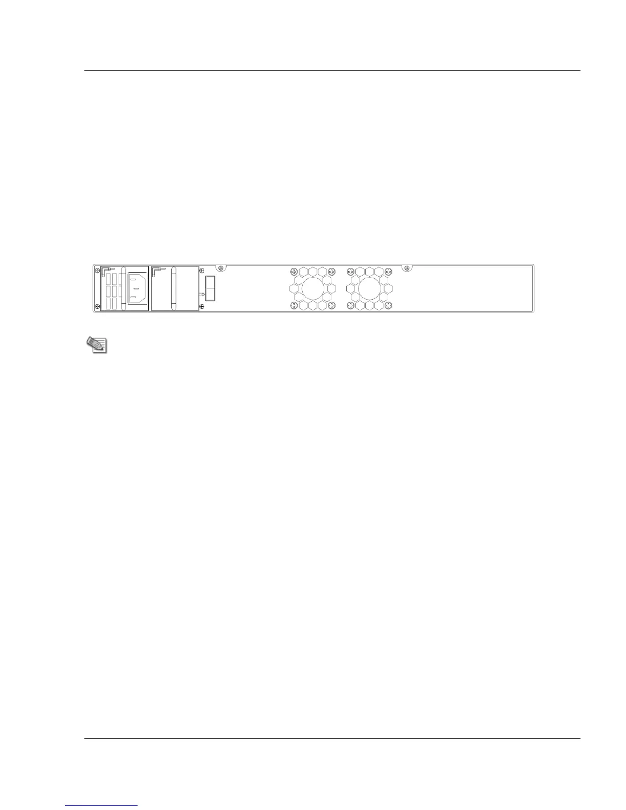
The Check Point 4800 has an optional redundant power supply unit. Located at the left rear of
the appliance, two hot-swappable power supply units give built-in power redundancy. Each
power supply connects to an electrical outlet.
For appliances that are provisioned with one power supply unit, use the placeholder unit in the
other power supply slot. This diagram shows the 4800 model with the placeholder unit:
If a power supply fails or is not connected to the outlet, an alarm sounds continuously.
Replacing and Upgrading Components
The Check Point 4000 Appliances has parts that you can easily replace to minimize downtime.
There are also upgrade components that you can install on the appliance. These are the parts
and components that can be used with the appliance:
Sliding rails
Line cards
Power supplies (4800 only)
System memory (4800 only)
LOM card (4800 only)
For more information about installing these parts and components, see the appliance home
page (http://supportcontent.checkpoint.com/solutions?id=sk68681).
Unless directed to do so by Check Point technical support, you are prohibited by warranty and
support agreements from replacing any parts.