Installation for Layer Cage Systems Only ULTRAFLO
®
Cage Feeding Systems for Brood Grow & Layer Installations
18
MC656P
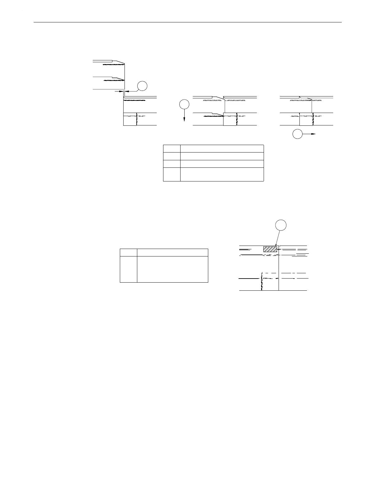
4.Overlap the straight end of the next Trough Section over the expanded end of the installed
trough approximately 1/4" (6 mm). Snap it down on the installed trough and slide the
Trough Sections together (See Figure 23.).
5.At the first two joints from each end of the Cage Row, fasten the trough joints together with
self-drilling screws (See Figure 24.).
6.Continue installing Trough Sections until a Power Unit location is reached.
7.See “Power Unit Installation” on page 23, of this manual, for power unit installation
instructions. Then, continue installing Trough Sections until another Power Unit location or
the end of the Cage Row is reached.
8.At the end of the Cage Row, cut the trough so that it extends past the end of the cage row 4"
(100 mm).
9.Slide an End Cap onto the Trough and fasten with self-drilling screws.
Key Description
1 1/4" (6 mm) Gap
2 Snap Down
3 Slide straight end of Trough into
belled end of the next Trough.
Figure 23.Trough Connection Diagram (side view).
MC656-32 9/9
Key Description
1 A self-drilling screw should
be installed in this area on the
first two trough joints from
both ends.
Figure 24.Trough Fastening Diagram (side view).
 Loading...
