Ground Bond Tester 19572 User’s Manual
4-10
4.8.3 Test Procedures
1. Follows DUT connection method to connect correctly.
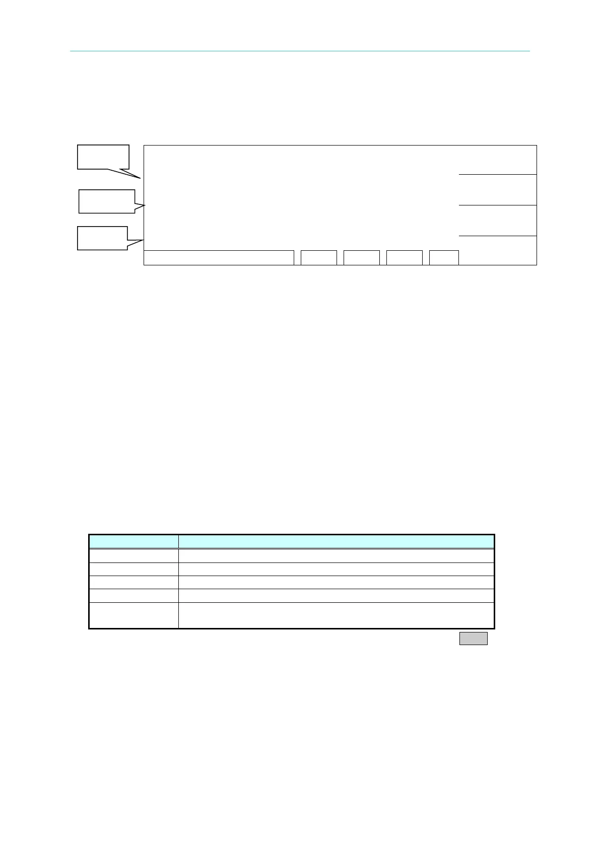
2. In power on menu (as below),
:
PROGRAM
PRESET
MENU
MORE..
Description:
STEP 1/2 means there are two test procedures, now is going to perform the first test
procedure. “Line 1” means test current setting value, “Line 2” means the high limit of
grounding resistance, “Line 3” means test time, the test result shows on status line.
1. Please press [STOP] ready for testing, the status line shows ” STANDBY”.
2. Press [START] to start test.
When press this key, it will start test current output. The DANGER LED light up in the
meantime, the status line show “ UNDER TEST”. Warning: Now is test status with mass
current output. “Line 1” shows the output current reading. “Line 2” shows the
measured resistance reading. “Line 3” the timer doing count down simultaneously.
3. Pass judgment
When all of test states have been tested and the test result shows PASS, then the main
machine is judged as PASS and cut off output. The rear panel output PASS signal and the
buzzer functioning simultaneously.
4. Fail judgment
If the measurement value is abnormal, the main machine is judged as FAIL and stop output
immediately. The rear panel output FAIL signal and the buzzer functioning simultaneously.
Keep on function until [STOP] key is pressed. The test result will show Fail state.
Fail state description table
Measurement resistance value is over high limit
Measurement resistance value is over low limit
Current reading is over hardware valid digit.
Resistance reading is over hardware valid digit.
TEST
Do not set the output current value or the measured resistance
high limit value.
Under any circumstance, if the test output to be stopped only need to press STOP.
4.9 KEY LOCK Function
4.9.1 KEY LOCK Setting
1. In Power On Menu, you can set KEY LOCK if “ LOCK” is not highlighted.
2. Press Function Key [MENU], the menu shown below.