Panel Description
4-15
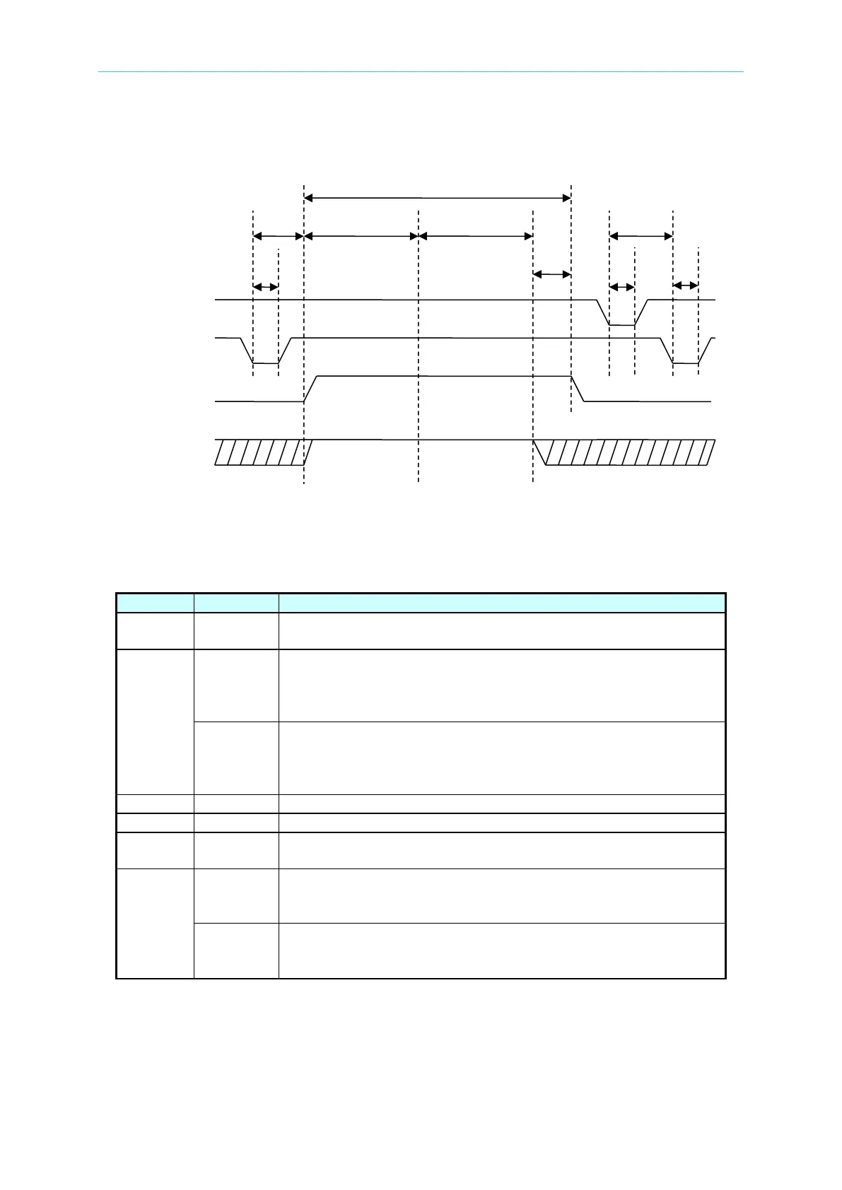
4.13 Timing Diagram
Timing diagram – take an example by two test steps
T1 > 20mS
The time of external trigger signal/START & /RESET to be
remained which needs larger than 20mS.
T2
< 200mS
The time of external trigger signal /START to /UNDER TEST
signal to be cleared, it will be smaller than 200mS. The previous
STEP test result /PASS signal status has been cleared in
< 300mS
The time of external trigger signal /START to /UNDER TEST
signal to be cleared,
it will be smaller than 300mS. The previous
STEP test result /PASS signal status hasn’t been cleared in
Test needed time of various test steps.
/Pass signal sent larger than 5mS, /UNDER TEST signal is end.
T5 -
The equipment used time as testing, the signal is simultaneous
with Danger lamp on panel.
T6
>160mS
The time of external trigger signal /RESET to /START signal to
be started which needs to be larger than 160mS (SCREEN
>250mS
The time of external trigger signal /RESET to /START signal to
be started which needs to be larger than 250mS (SCREEN
 Loading...


