General Information
1-5
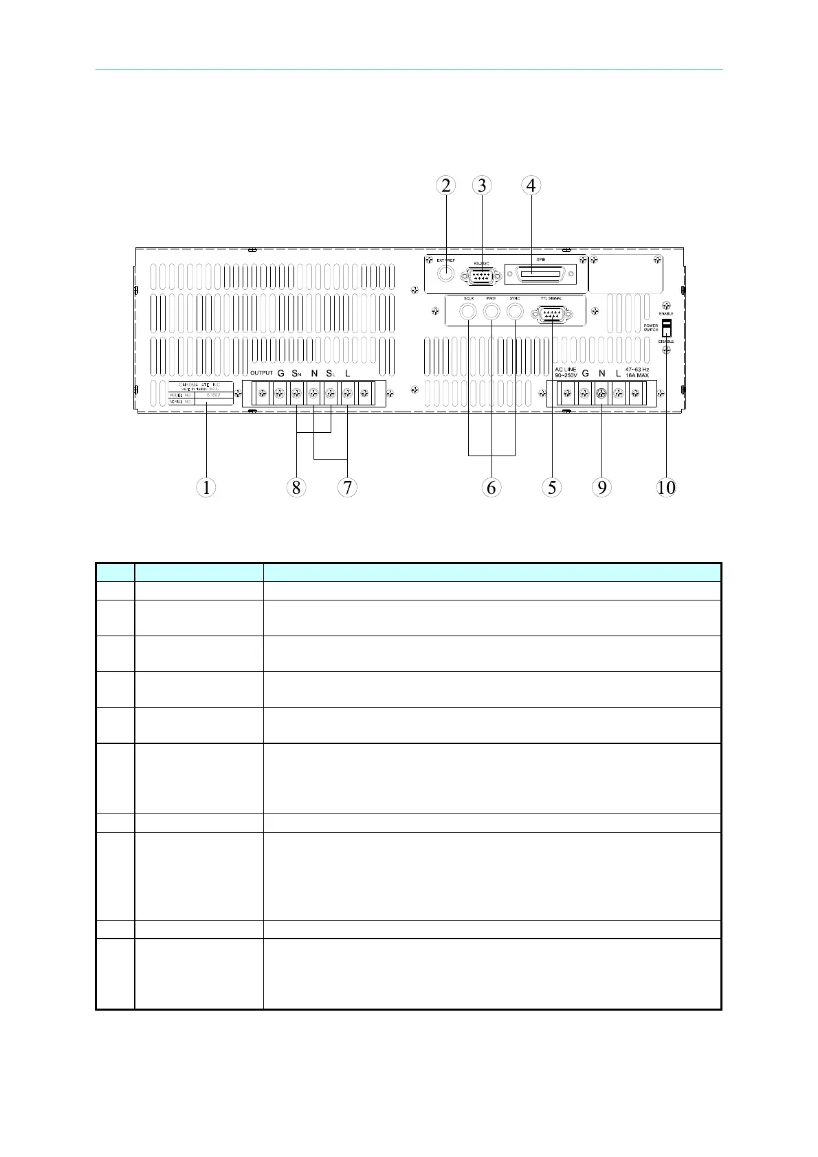
1.4.2 Rear Panel
Figure 1-2 Rear Panel
Table 1-2 Description of Rear Panel
Item Name Description
1 Label The label includes model number, series number of the AC source.
2 Ext. Ref.
The BNC connector inputs control waveform amplitude from
external analog signal.
3
RS-232C
The 9-pin, D-type female connector transfers control commands to
and from the remote PC for remote operation.
4 GPIB Connector
A remote controller using GPIB bus is connected to the AC source
through this connector for remote operation.
5
TTL Signal The 9-pin, female connector transfers control signals (fault_out,
remote inhibit, and AC_ON).
6 SCLK, PWM,
SYNC
The BNC connectors SCLK and PWM are for AC source parallel
connectivity only. SYNC transfers a pulse signal synchronously
when output changes. It also sends synchronizing signal for
3-phase mode operation.
7 Output Connector This connector outputs power to the loading device.
8 Remote Sense
Connector
It senses directly at the terminals of the load to eliminate any
voltage drop on the connecting cable. Make sure of connecting
the terminal “SL” of the remote sense connector to the terminal “L”
of the load, and the “SN” to the “N” of the load. Reverse polarity is
not allowed.
9 Power Line Power line input is connected to AC source through this connector.
10 Power Switch It enables or disables the main power switch. Users can power on
or off with the main power switch when the power switch is set to
“ENABLE”. Conversely the main power switch is inactive when the
power switch on the front panel is set to “DISABLE”.