Installation
2-3
2.4 Output Connection
The output terminal block is located on the rear of AC source. Load connecting to the "N"
and "L" is done at the output terminals. To meet the safety requirements, the safety cover
must be fastened. The wires to the load must be sufficiently large gauges, so they will not
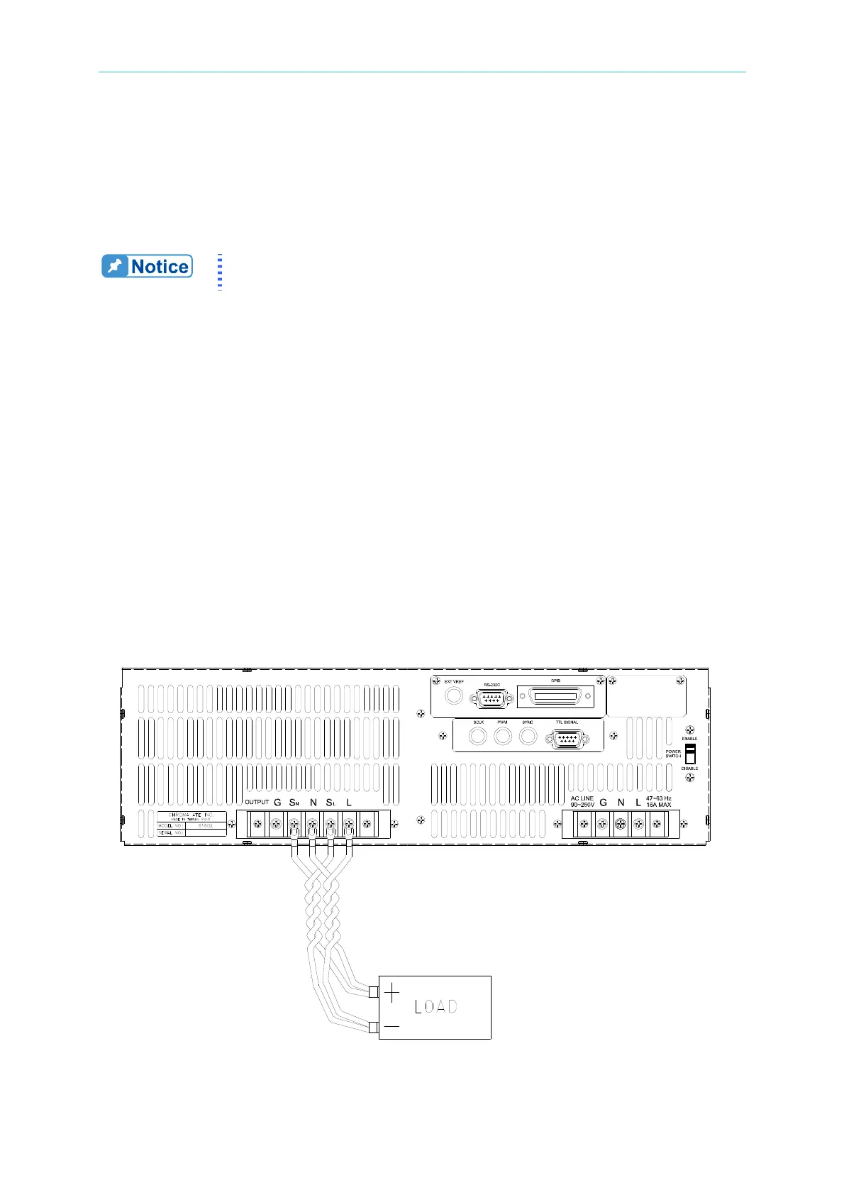
overheat while carrying the output current. Please see Figure 2-3 on the next page.
Output terminal labeled "L" is the "+" terminal, terminal labeled "N" is the
"-" terminal when output voltage contains DC composition.
2.5 Remote Sense Connection
The remote sense function of AC source monitors the voltage at the load instead at the
output terminal of the AC source. It ensures the delivery of accurate voltage as
programmed at the load by automatically compensating the output voltage drop over the
connecting cable.
Remove the iron chip from the “S
N” and “SL” terminals, connect the remote sense to the load
as shown in Figure 2-3. Because the sensing leads carry only a few milliamperes, the wires
for sensing
are much lighter than the load leads. The sensing leads are part of the
feedback path of the AC source, so they must be kept at a low resistance in order to maintain
the best performance. Connect the sensing leads carefully so that they will not be
open-circuited. If the sensing leads are left unconnected or become open-circuited during
operation, the AC source will disable the output. The sensing leads must be a twisted pair
to minimize the pickup of external noise. The sensing leads need to be connected to the
load as close as possible.
Figure 2-3 Output & Remote Sense Connection