Programmable AC Source 61501/61502/61503/61504 User’s Manual
3-4
3.3 MAIN PAGE (Output Setting and Measurement)
When the user turn on the AC source, after self-test steps, the display shows the MAIN
PAGE. The upper line of display shows the output settings. The state of default output
settings can be set on POWER ON STATUS in CONF functional list (see 3.6.3). The lower
lines show the measurements of AC source outp
ut. Please see the following.
Press
SHIFT, then or to change to next page. Please see the following.
On the right-up side of display, a letter "L" shows the status of RANGE (see 3.5.1). The
definition of
letters:
L : 150V RANGE
H : 300V RANGE
H : 600V RANGE
A : AUTO RANGE
The definitions of output setting parameters:
Vac : It is the AC composition of output voltage in Volts.
F : It is the output frequency in Hertz.
Vdc : It is the DC composition of output voltage in Volts.
Press OUT/QUIT then the AC source output the voltage set in Vac, F, Vdc. Press OUT/QUIT
again, then the AC source quit the output voltage.
When COUPLE = AC+DC, the output is the combination of Vac and Vdc.
But the combination of peak voltage can not exceed the limit of each
range (150V RANGE: 212.1V, 300V RANGE: 424.2V). If it is
happened, the output voltage will quit to 0V automatically, and show the
protection condition.
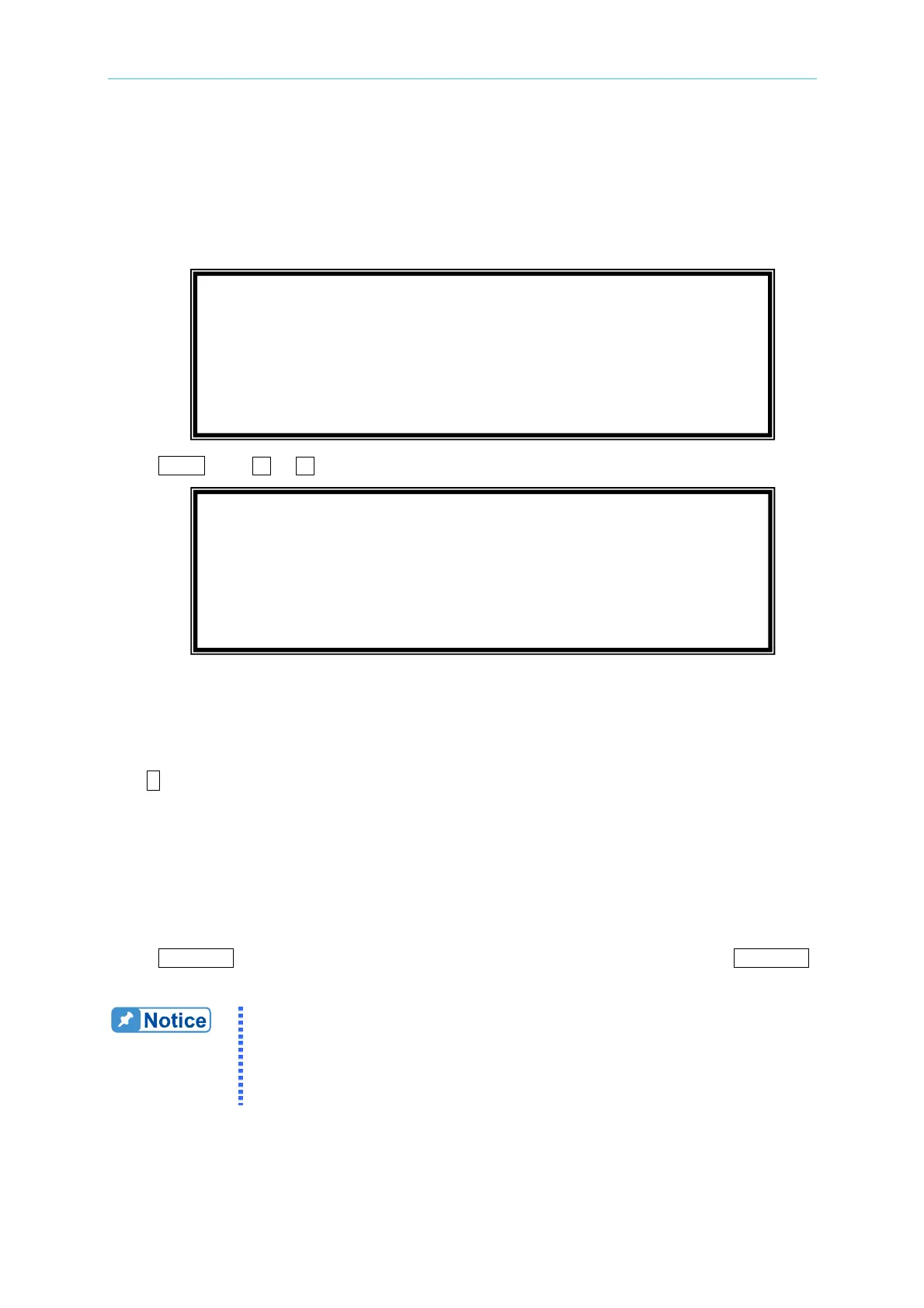
Vac = 0.0 F = 60.00 Vdc = 0.0 L
V
= 0.00 F = 0.00 I = 0.00 S
P
= 0.0 PF = 0.000 CF = 0.00 T
Vac = 0.0 F = 60.00 Vdc = 0.0 L
Vdc = 0.00 Idc = 0.00 Ip = 0.0 S
Is = 0.0 VA = 0.0 VAR = 0.0 T