Appendix A Pin Assignment of TTL Signal
A-1
Appendix A Pin Assignment of TTL
Signal
9-Pin D-Type Male Connector:
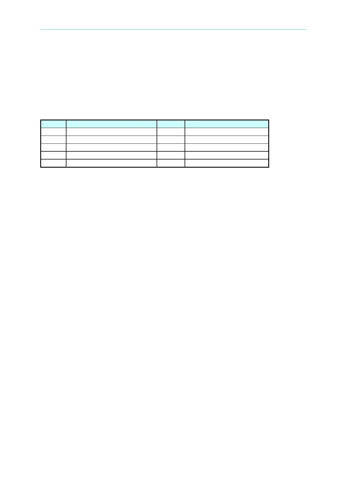
Pin No. Signal Pin No. Signal
1 GND 6 GND
2 / Remote-Inhibit 7 GND
3 GND 8 / FAULT-OUT
4 AC-ON 9 ---
5 ---
/ Remote-Inhibit: When voltage level of this pin becomes LOW, it can inhibit the output
of AC source, or excite the action of mode ( See 3.6.1 ).
AC-ON: When AC source output voltage, this pin will becomes HIGH, and it
becomes LOW when quit output.
/ FAULT-OUT: The voltage level of this pin is HIGH if AC source is in normal state. It
becomes LOW when AC source is in protection state.
Connecting the / FAULT-OUT signal of TTL PIN8 on AC Source rear panel to TTL PIN8 on
A615003 rear panel as turning on the functions of A615003 thus it can be activated.