Local Operation
3-11
3.6.1 REMOTE INHIBIT
The output of the AC Source can be inhibited by the external control or by manual trigger.
The remote inhibit signal is received from 9-pin female connector on the rear panel (see
Appendix A). Users can set REMOTE INHIBIT on CONF functional list (see 3.6). There
are three states for remote inhibit: OFF, LIVE, and TRIG.
OFF: It disables the feature of remote inhibit.
LIVE: The output of the AC Source will be disabled if TTL signal is LOW, but will be
recovered automatically if TTL signal is HIGH.
TRIG: The output of the AC Source will be disabled if TTL signal is LOW, and will remain in
quit state even TTL signal becomes HIGH.
The procedures of setting from OFF to LIVE are shown as below:
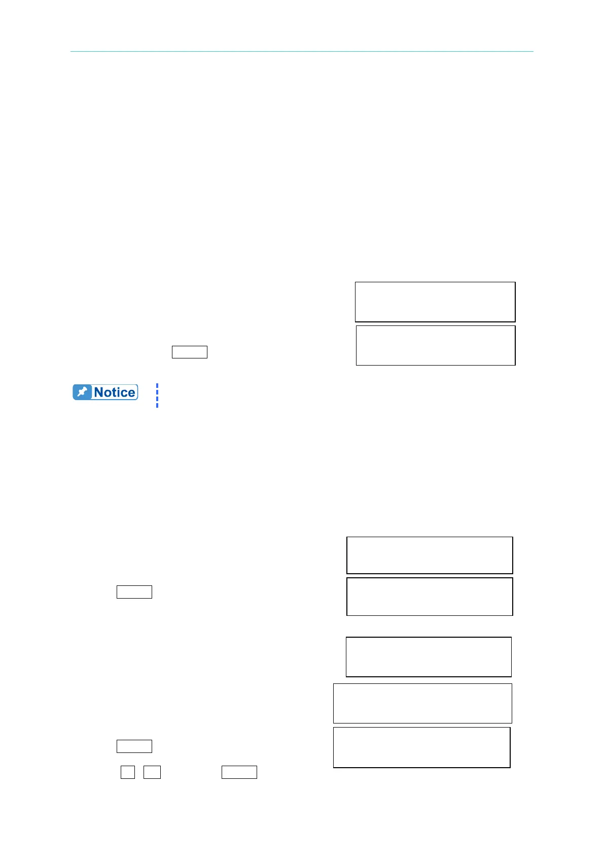
1. Move the cursor to the command of "REMOTE
INHIBIT" to set inhibition by the TTL signal from REMOTE INHIBIT =OFF_
the external control.
2. Turn the RPG to change the option from OFF to REMOTE INHIBIT =LIVE
LIVE, then press ENTER.
The remote inhibit is a TTL signal transferred via the special I/O
connector. For details please refer to the pin assignment in Appendix A.
3.6.2 WAVEFORM GENERATOR (Optional Function)
The AC Source provides users with two independent sets of waveforms, A and B in each
phase. Both of the waveforms contain sinusoidal, square, clipped sinusoidal, 30 sets of
built-in waveforms, and 6 sets of user-defined waveforms.
To set Φ1 waveform A as square wave:
1. Move the cursor to the command of WAVEA[Φ1]. WAVEA[Φ1]= SINE_
2. Turn the RPG to change the option to “SQR”, then
press ENTER . WAVEA[Φ1]=SQR_
To set Φ1 waveform B as clipped Sin wave, THD: 10 %
1. Move the cursor to command of WAVE B, WAVEB[Φ1]=CSIN_
choose “CSIN”.
2. Then, LCD display shows the MODE and MODE = AMP_ PER = 0.0 %
PERCENT.
3. Turn the RPG to change the option to “THD”,
press ENTER . MODE = THD PER = 0.0_ %
4. Press 1 , 0 then press ENTER to set