CHRYSLER SERVICE MANUAL
FRONT WHEEL SUSPENSION—5
UPPER CONTROL ARM*
|57x59f
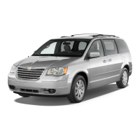
Fig.
4—Upper Control Arm, Shim Pack and Bracket
/'/STEERING
KNUCKLE7\
f
fJBK*.IJPP5
CONTROL"ARM BALL JOINT
STRUT MOUNTING BOLTS
LOWER CONTROL
ARM
BALL JOINT
Fig.
7—Steering Knuckle and Ball Joint Assembly
COTTER
PIN
NUT
WASHER
57x63
A
WASHER
NUT
TORSION
BAR
COTTER
PIN
LOWER CONTROL
ARM
Fig.
5—Lower Control Arm Pivot Shaft and Bushing Assembly
SWAY
BAR
STRUT
BAR
BUSHING
LOWER CONTROL
ARM
SWAY
BAR
BUSHING
x268
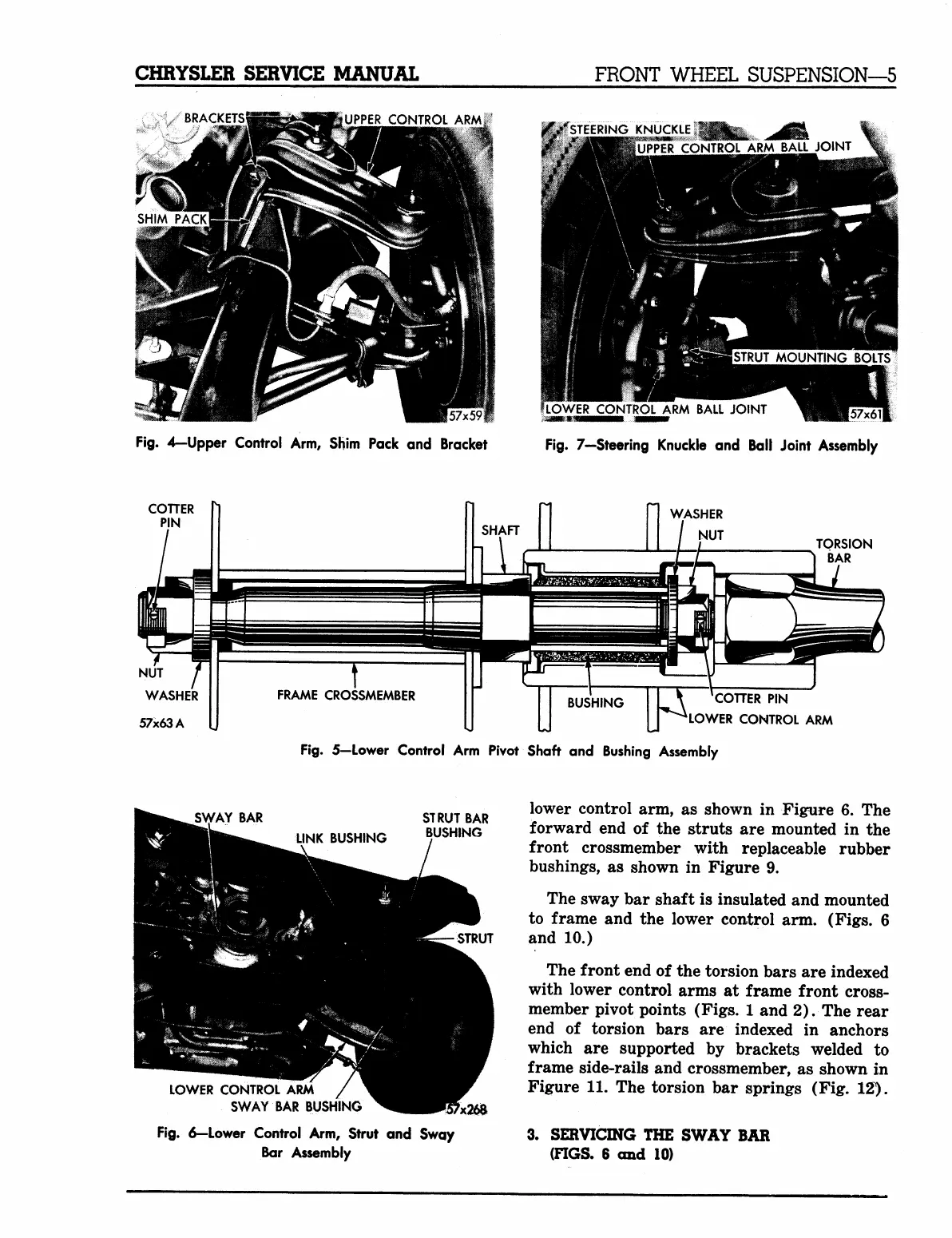
Fig.
6—Lower Control Arm, Strut and Sway
Bar
Assembly
lower control arm, as shown in Figure 6. The
forward end of the struts are mounted in the
front crossmember with replaceable rubber
bushings, as shown in Figure 9.
The sway bar shaft is insulated and mounted
to frame and the lower control arm. (Figs. 6
and 10.)
The front end of the torsion bars are indexed
with lower control arms at frame front cross-
member pivot points (Figs. 1 and 2). The rear
end of torsion bars are indexed in anchors
which are supported by brackets welded to
frame side-rails and crossmember, as shown in
Figure 11. The torsion bar springs (Fig. 12).
3.
SERVICING THE SWAY BAR
(FIGS. 6 and 10)
MyMopar.com
 Loading...