17
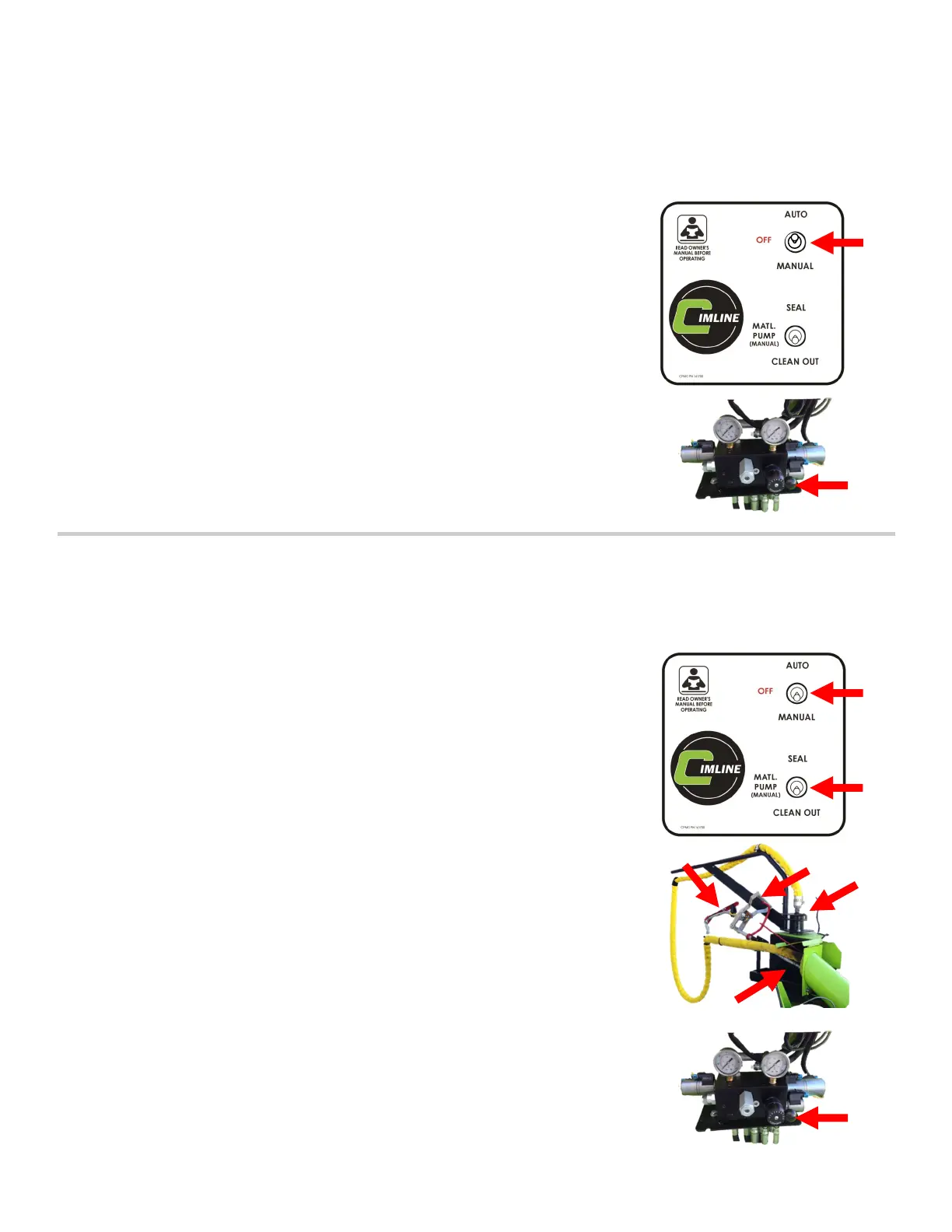
METHOD #1
1. SET AUXILIARY HOSE CONTROL PANEL SWITCH (A) TO “AUTO”:
The clean out function on the auxiliary hose will run concurrently with
the primary hose cleanout procedure on the main control box.
Follow all instruction for the auxiliary hose as you would on the primary
hose (as described on the previous page).
Make certain to set rotary switch (B) on the hydraulic block to “9” for
maximum sealant material flow during the clean out process.
The entire procedure (steps A - G) on the previous page should be fol-
lowed and all steps properly executed for the auxiliary hose. Following
this process fully will increase start up efficiency on the next job.
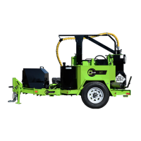
METHOD #2
1. SET AUXILIARY HOSE CONTROL PANEL SWITCH (A) TO “MANUAL”
2. SET THE MATERIAL PUMP SWITCH (B) TO “CLEAN OUT”:
The clean out function on the auxiliary hose will run independently of
the primary hose cleanout procedure on the main control box.
The entire procedure (steps A - G) should be followed and all steps
properly executed for the auxiliary hose. Following this process fully
will increase start up efficiency on the next job.
A) Place the auxiliary wand in the secondary recirculation port (C)
and pin the trigger (D).
B) If your wand has a manual valve, move the handle forward to
open the manual valve on the wand (E).
C) Set rotary switch (G) on the hydraulic block to “9” for maximum
sealant material flow during the clean out process.
D) Allow the unit to run for 5 minutes to evacuate as much of the
sealant material back to the tank as possible.
E) After 5 minutes, unpin the wand trigger, pull the handle back on
the manual valve to close the valve and remove the wand from
the recirculation port.
F) Properly secure the wand in the auxiliary storage tray.
G) Swing the boom all the way forward and lock the boom using
the locking pin (F).
M4 Dual Hose Clean Out / Shut Down Procedure
(A)
(B)
(D)
(E)
(F)
(C)
(G)
(A)
(B)