27
M-Series Maintenance - Recirculation Valve Timing
SEALANT MATERIAL RECIRCULATION VALVE:
The material sealant pumping system relies on a mechanical valve to direct the flow of material either
to the application hose and wand or in recirculation mode back to the tank. This valve is operated by a
hydraulic actuator and is connected to the recirculation valve shaft by a clamp and two set screws.
This system is intentionally designed to slip when under extreme force to prevent damage to the valve
or the hydraulic actuator. If the system is activated when cold material is inside the valve the actuator
may try to operate the valve and not be able to move due to the cold material impeding proper
operation of the valve interior. Thus the clamp will slip on the shaft and be out of time with the proper
operation to apply sealant or recirculate material back to the tank.
Correct Position for
Material Flow Between Application and Recirculation:
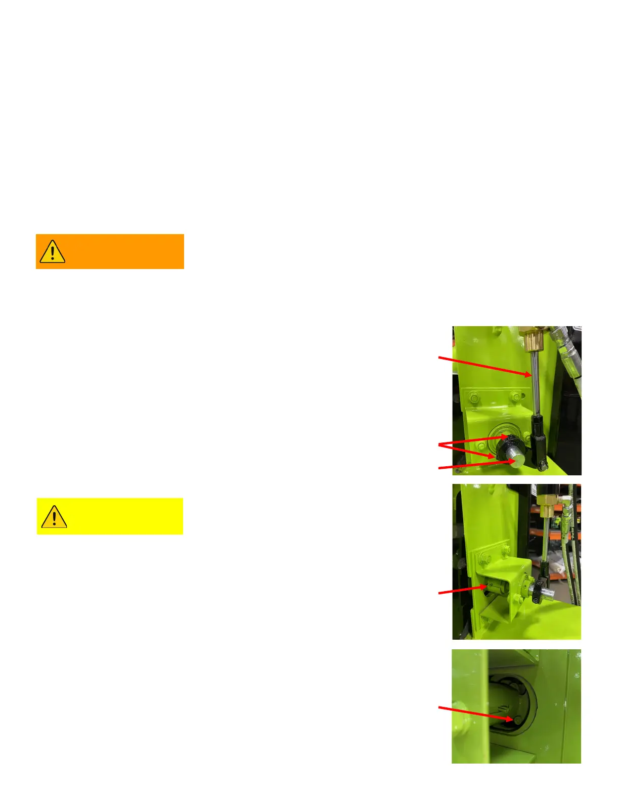
a) The first photo shows the hydraulic actuator (A) fully extended
and in the recirculation position. This is the correct position for
the valve and hydraulic actuator when the system is not calling
for sealant to the applicator hose and wand.
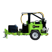
b) The second photo again shows the recirculation valve in the
correct position for recirculation as indicated by the roll pin (B)
being in the horizontal (9 o’clock - 3 o’clock) position. When the
hydraulic actuator retracts it turns the valve shaft in a counter
clockwise direction and the roll pin (B) will be in a vertical (12
o’clock - 6 o’clock) position.
INSTRUCTIONS FOR RESETTING THE TIMING OF THE
RECIRCULATION VALVE:
It may be necessary to run the melter up
to temperature in order to successfully
operate the valve when making this
timing adjustment. Extreme caution
must be taken when working around hot material and hot melter
machine parts.
1) Loosen the two hex head screws (C) on the clamp from the
hydraulic actuator to the recirculation valve shaft.
2) Using a locking plyers or pipe wrench rotate the recirculation
valve shaft (D) until the roll pin is in the correct orientation -
horizontal (9 o’clock - 3 o’clock) position.
3) With the hydraulic actuator extended in the recirculation position
and the roll pin on the valve shaft in the horizontal (9 o’clock - 3
o’clock) position, tighten the two hex head screws (C) on the
clamp, torque to 22 ft. lbs.
4) In some rare occasions the recirculation valve limit set screw
will need to be adjusted . The limit screw is shown in the photo
as (E).
(B)
(A)
(C)
(D)
(E)
The melter operates at elevated temperatures which can cause
burns. Be sure the sealant material is cool before performing
maintenance.
WARNING
CAUTION