47
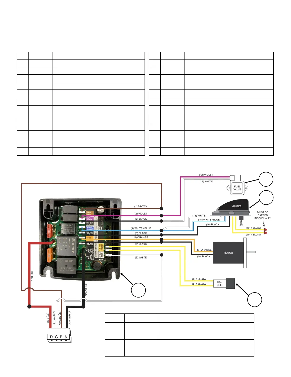
Tank Burner Internal Wiring Diagram
# COLOR DESCRIPTION
# COLOR DESCRIPTION
1 Brown Alarm To Controller
12 Violet Fuel Valve Input Lead
2 Violet Fuel Valve To Controller 13 White Fuel Valve Ground Lead
3 Black Fuel Valve Ground To Controller 14 White Secondary Igniter Input Lead
4 Wht/Blu Igniter To Controller 15 Wht/Blu Primary Igniter Input Lead
5 Black Igniter Ground To Controller 16 Black Igniter Ground Lead
6 Orange Motor To Controller 17 Orange Motor Input Lead
7 Black Motor Ground To Controller 18 Black Motor Ground Lead
8 Yellow Cad Cell To Controller (x2) 19 Yellow Not Used (Capped Individually) X2
9 White Control Circuit Enable To Controller 20 Red 12V (+) Power (Wiring Harness)
10 Red 12V (+) Input To Controller 21 White Burner Enable (Wiring Harness)
11 Black Ground (-) To Controller 22 Brown LOFA Alarm (Wiring Harness)
23 Black Ground From Relay (Wiring Harness)
1
3
4
# Part # Description
1 200352 Burner Primary Controller
2 155001 Burner Fuel Pump
3 152173 Burner Ignition Transformer Assembly
4 152105 Burner Cad Cell (Electric Eye)
2