FIGURES
ix
Cisco 12000 Series Router SIP and SPA Hardware Installation Guide
Release 12.0(32)SY1, OL-8831-01, Rev. G6, July 19, 2007
Figure 1-1 Cisco 12000 SIP-400 Board—Rear View 1-5
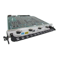
Figure 1-2 Cisco 12000 SIP-400 Face Plate 1-5
Figure 1-3 Cisco 12000 SIP-400 with SPAs Installed 1-6
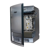
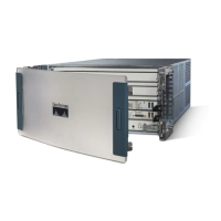
Figure 1-4 Cisco 12000 Series Router with Cisco 12000 SIP-400 Installed 1-7
Figure 1-5 Cisco 12000 SIP-600 Board—Rear View 1-8
Figure 1-6 Cisco 12000 SIP-600 Face Plate 1-8
Figure 1-7 Subslot Locations for the 1-Port 10-Gigabit Ethernet SPA 1-9
Figure 1-8 Slot, Subslot, and Port Locations for the 1-Port 10-Gigabit Ethernet SPA and the 10-Port Gigabit Ethernet
SPA.
1-10
Figure 1-9 Cisco 12000 SIP-401 Board—Rear View 1-11
Figure 1-10 Cisco 12000 SIP-401 Face Plate 1-12
Figure 1-11 Cisco 12000 SIP-401 with SPAs Installed 1-13
Figure 1-12 Cisco 12000 Series Router with Cisco 12000 SIP-401 Installed 1-14
Figure 1-13 Cisco 12000 SIP-501 Board—Rear View 1-15
Figure 1-14 Cisco 12000 SIP-501 Face Plate 1-15
Figure 1-15 Subslot Locations for the 1-Port 10-Gigabit Ethernet SPA 1-16
Figure 1-16 Slot, Subslot, and Port Locations for the 1-Port 10-Gigabit Ethernet SPA and the 10-Port Gigabit Ethernet
SPA.
1-17
Figure 1-17 Cisco 12000 SIP-601 Board—Rear View 1-18
Figure 1-18 Cisco 12000 SIP-601 Face Plate 1-19
Figure 1-19 Subslot Locations for the 1-Port 10-Gigabit Ethernet SPA 1-20
Figure 1-20 Slot, Subslot, and Port Locations for the 1-Port 10-Gigabit Ethernet SPA and the 10-Port Gigabit Ethernet
SPA.
1-21
Figure 2-1 4-Port Clear Channel T3/E3 SPA Faceplate 2-4
Figure 2-2 4-Port Channelized T3 SPA Faceplate 2-6
Figure 2-3 8-Port Channelized T1/E1 SPA Faceplate 2-8
Figure 2-4 RJ-45 Connector 2-9
Figure 2-5 8-Port FastEthernet SPA Faceplate 2-10
Figure 2-6 RJ-45 Connections, Plug, and Receptacle 2-11
Figure 2-7 Straight-Through Cable Pinout, RJ-45 Connection to a Hub or Repeater 2-12
Figure 2-8 Crossover Cable Pinout, RJ-45 Connections Between Routers 2-12

 Loading...

