3-14
Cisco 2600 Series Routers Hardware Installation Guide
OL-2171-02
Chapter 3 Installing the Router
Connecting the DC Power Supply
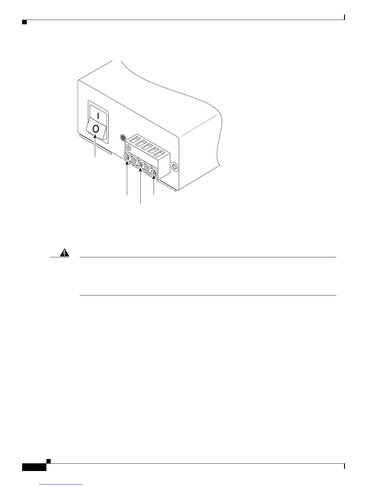
Figure 3-19 DC-Input Power Supply Terminal Block
Step 3 Strip 3/16 in. of shielding from the free end of each power lead wire that is attached to the DC-input
power supply.
Step 4 Insert the three power leads into the slotted wire receptacles on the terminal block. (See Figure 3-20.)
Warning
The illustration shows the DC power supply terminal block. The proper wiring sequence is ground
to ground, positive to positive (line to L), and negative to negative (neutral to N). Note that the
ground wire should always be connected first and disconnected last. To see translations of the
warnings that appear in this publication, refer to the Regulatory Compliance and Safety
Information document that accompanied this device.
30054
+ –
On/off
switch
Ground
Negative
Positive
 Loading...