3-17
Cisco 2600 Series Routers Hardware Installation Guide
OL-2171-02
Chapter 3 Installing the Router
Power on the Router
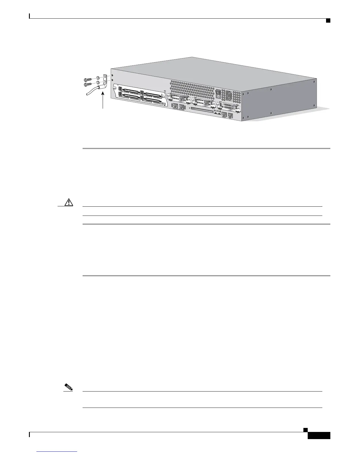
Figure 3-23 Attaching Grounding Lug on Cisco 2691
Step 5 Connect the other end of the ground lug wire to a grounding point at your site.
Step 6 Reconnect power and interface cables.
Power on the Router
Take the following steps to power on the router:
Caution Secure all power cabling when installing this unit to avoid disturbing field-wiring connections.
Step 1 a. For routers with AC input, plug the router's power cord into a three-terminal, single-phase power
source that provides power within the acceptable range.
b. For routers with DC input, follow the instructions in the “Wiring the DC Power Supply” section on
page 3-13.
Step 2 Power ON the router. The LED labeled SYSTEM on the front panel is on.
Connecting to a Network
Connecting to a LAN
This section explains how to use the Ethernet and/or Token Ring ports to connect the router to the LAN.
• The basic Ethernet and Token Ring cables required to connect the router to a network are provided
with the router. (See Table 3-1.)
• For cable pinouts, refer to the online document Cisco Modular Access Router Cabling
Specifications on the Documentation CD-ROM that came with your router and on Cisco.com.
Note Although the illustrations in this section show the Cisco 2611 router, the procedures are the same for
all of the Cisco 2600 series routers.
Ground lug
attachment
72228
EN
A
S
Y
N
C
A
S
Y
N
C
8
-
1
5
A
S
Y
N
C
0
-
7
1
5
1
4
1
3
1
2
1
1
1
0
9
8
7
6
5
4
3
2
1
0
A
S
Y
N
C
2
4
-
3
1
A
S
Y
N
C
1
6
-
2
3
3
1
3
0
2
9
2
8
2
7
2
6
2
5
2
4
2
3
2
2
2
1
2
0
1
9
1
8
1
7
1
6
S
E
E
M
A
N
U
A
L
B
E
F
O
R
E
IN
S
T
A
L
L
A
T
IO
N
C
O
N
SO
L
E
A
UX
FA
S
T
E
T
HE
R
N
ET
0
/1
F
AS
T
ET
H
ER
N
ET
0
/0
AL
CD
LP
RD
TD
S
E
E
M
A
N
U
A
L
B
E
F
O
R
E
IN
S
T
A
L
L
A
T
IO
N
D
S
U
5
6
K
AL
CD
LP
RD
TD
S
E
E
M
A
N
U
A
L
B
E
F
O
R
E
IN
S
T
A
L
L
A
T
IO
N
D
S
U
5
6
K
A
CT
10
0 M
bps
LINK
AC
T
10
0 M
bp
s
LIN
K
CF
1
C
IS
C
O
2
6
9
1
 Loading...