7-10
Firepower 7000 and 8000 Series Installation Guide
Chapter 7 Hardware Specifications
Firepower 7000 Series Devices
Use the following table to understand the bypass LED on the copper interfaces.
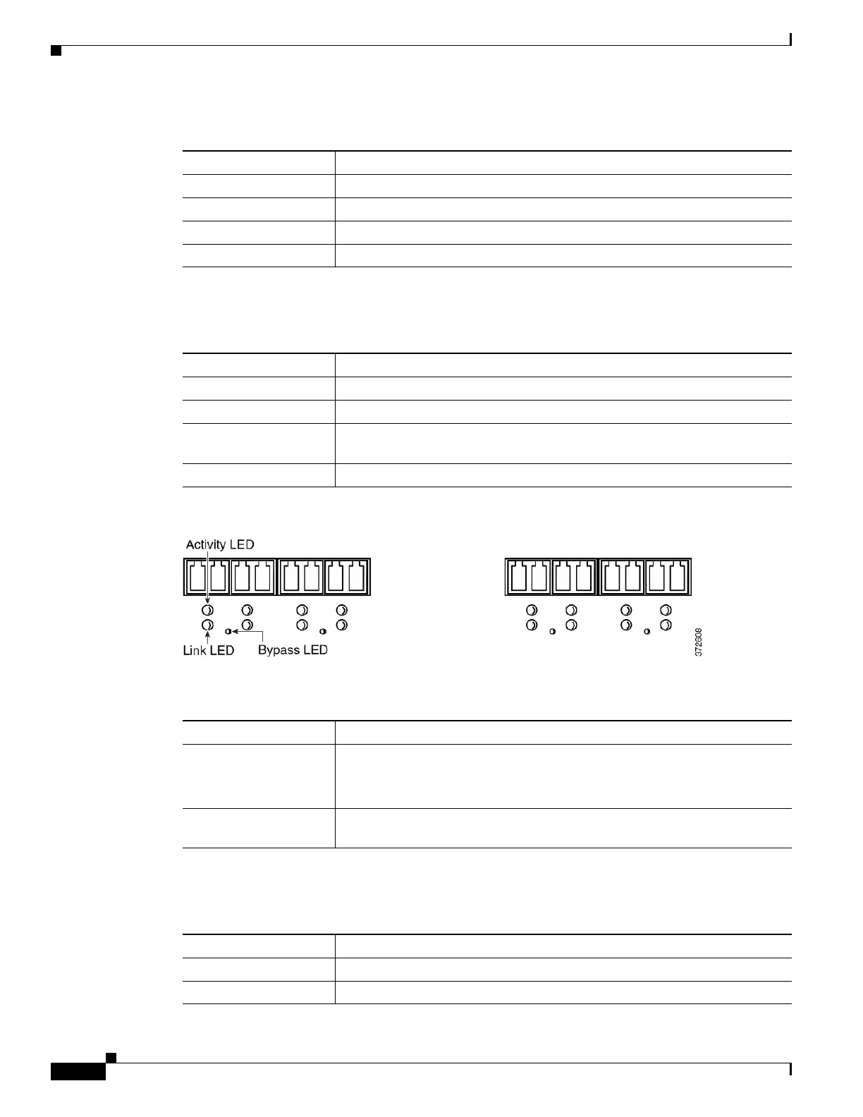
Figure 7-9 Eight-Port 1000BASE-SX Fiber Configurable Bypass Interfaces
Use the following table to understand the link and activity LEDs on the fiber interfaces.
Use the following table to understand the activity and link LEDs on the fiber interfaces.
Table 7-14 Firepower 7110 and 7120 Copper Link/Activity LEDs
Status Description
Both LEDs off The interface does not have link.
Link amber The speed of the traffic on the interface is 10Mb or 100Mb.
Link green The speed of the traffic on the interface is 1Gb.
Activity blinking green The interface has link and is passing traffic.
Table 7-15 Firepower 7110 and 7120 Copper Bypass LED
Status Description
Off The interface pair is not in bypass mode or has no power.
Steady green The interface pair is ready to enter bypass mode.
Steady amber The interface pair has been placed in bypass mode and is not inspecting
traffic.
Blinking amber The interface pair is in bypass mode; that is, it has failed open.
Table 7-16 Firepower 7110 and 7120 Fiber Link/Activity LEDs
Status Description
Top (activity) For an inline interface: the light is on when the interface has activity. If dark,
there is no activity.
For a passive interface: the light is non-functional.
Bottom (link) For an inline or passive interface: the light is on when the interface has link.
If dark, there is no link.
Table 7-17 Firepower 7110 and 7120 Fiber Bypass LEDs
Status Description
Off The interface pair is not in bypass mode or has no power.
Steady green The interface pair is ready to enter bypass mode.