7-11
Firepower 7000 and 8000 Series Installation Guide
Chapter 7 Hardware Specifications
Firepower 7000 Series Devices
Firepower 7110 and 7120 Chassis Rear View
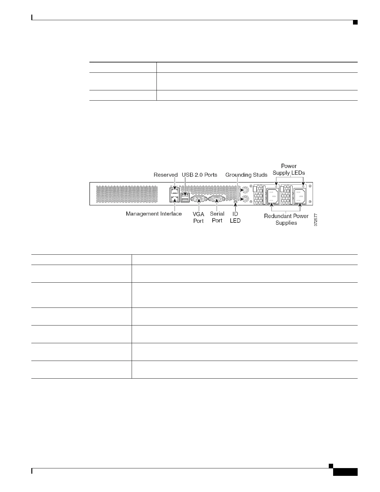
The rear of the chassis contains the management interface, connection ports, grounding studs, and power
supplies.
Figure 7-10 Firepower 7110 and 7120 (Chassis: GERY-1U-8-C-AC or GERY-1U-8-FM-AC) Rear View
The following table describes the features that appear on the rear of the appliance.
The 10/100/1000 management interface is located on the rear of the appliance. The following table
describes the LEDs associated with the management interface.
Steady amber The interface pair has been placed in bypass mode and is not inspecting
traffic.
Blinking amber The interface pair is in bypass mode; that is, it has failed open.
Table 7-17 Firepower 7110 and 7120 Fiber Bypass LEDs (continued)
Status Description
Table 7-18 Firepower 7110 and 7120 System Components: Rear View
Features Description
VGA port
USB port
Allows you to attach a monitor, keyboard, and mouse to the device to establish a direct
workstation-to-appliance connection.
10/100/1000 Ethernet management
interface
Provides for an out-of-band management network connection. The management
interface is used for maintenance and configuration purposed only and is not intended
to carry service traffic.
System ID LED Helps identify a system installed in a high-density rack with other similar systems.
The blue light indicates that the ID button is pressed.
Grounding studs Allows you to connect the appliance to the Common Bonding Network. See the Power
Requirements for Firepower Devices, page A-1 for more information.
Redundant power supplies Provides power to the device through an AC power source. Looking at the rear of the
chassis, power supply #1 is on the left and power supply #2 is on the right.
Power supply LEDs Indicates the status of the power supply. See Table 7-20Firepower 7110 and 7120
Power Supply LED, page 7-12.