7-23
Firepower 7000 and 8000 Series Installation Guide
Chapter 7 Hardware Specifications
Firepower 8000 Series Devices
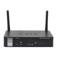
Figure 7-17 Firepower 82xx Family (Chassis: CHAS-2U-AC/DC) and Firepower and AMP 83xx
Family (PG35-2U-AC/DC) Front View
The following table describes the features on the front of the appliance.
See the following sections for more information:
• Firepower 8000 Series Front Panel, page 7-23
• Firepower 8000 Series Chassis Rear View, page 7-26
Firepower 8000 Series Front Panel
The front panel for the Firepower and AMP 81xx Family, 82xx Family, and 83xx Family contain the
same components.
Figure 7-18 Firepower 81xx Family Front Panel
Table 7-34 Firepower 8000 Series System Components: Front View
Feature Description
Module slots Contain the modules. For information on available modules, see Firepower
8000 Series Modules, page 7-32.
LCD panel Operates in multiple modes to configure the device, display error messages,
and view system status. For more information, see Using the LCD Panel on
a Firepower Device, page 6-1.
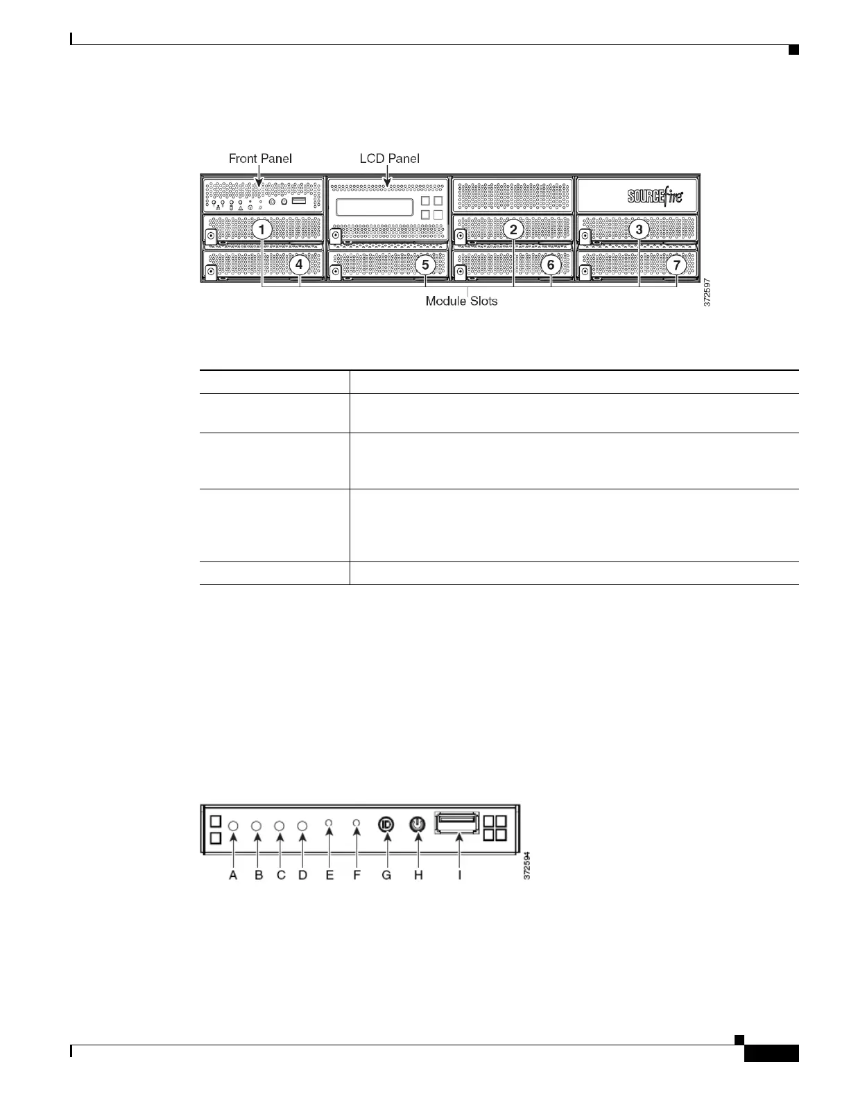
Front panel controls Houses LEDs that display the system’s operating state, as well as various
controls, such as the power button. For more information, see
Figure 7-19Firepower 82xx Family and Firepower and AMP 83xx Family
Front Panel, page 7-24.
Front panel USB port The USB 2.0 port allows you to attach a keyboard to the device.