StatusColorLED
Output power is enabled.
GreenOutput OK
Output power in power limit, or in overcurrent
condition, or is in the sleep-mode.
1
Flashing Green
Output disabled, or no inputs present, or firmware
upgrade in-progress.
Off
Output voltage is out of the specified range, or a fan
has failed, or internal fault.
RedFault
Firmware upgrade in-progress.Flashing red
User configured action conf ig hw-module attention-led
location 0/PTx/PMy.
Flashing blueATTN (Attention)
No user configuration is set.Off
1
Sleep mode is not applicable for DC-60 power module.
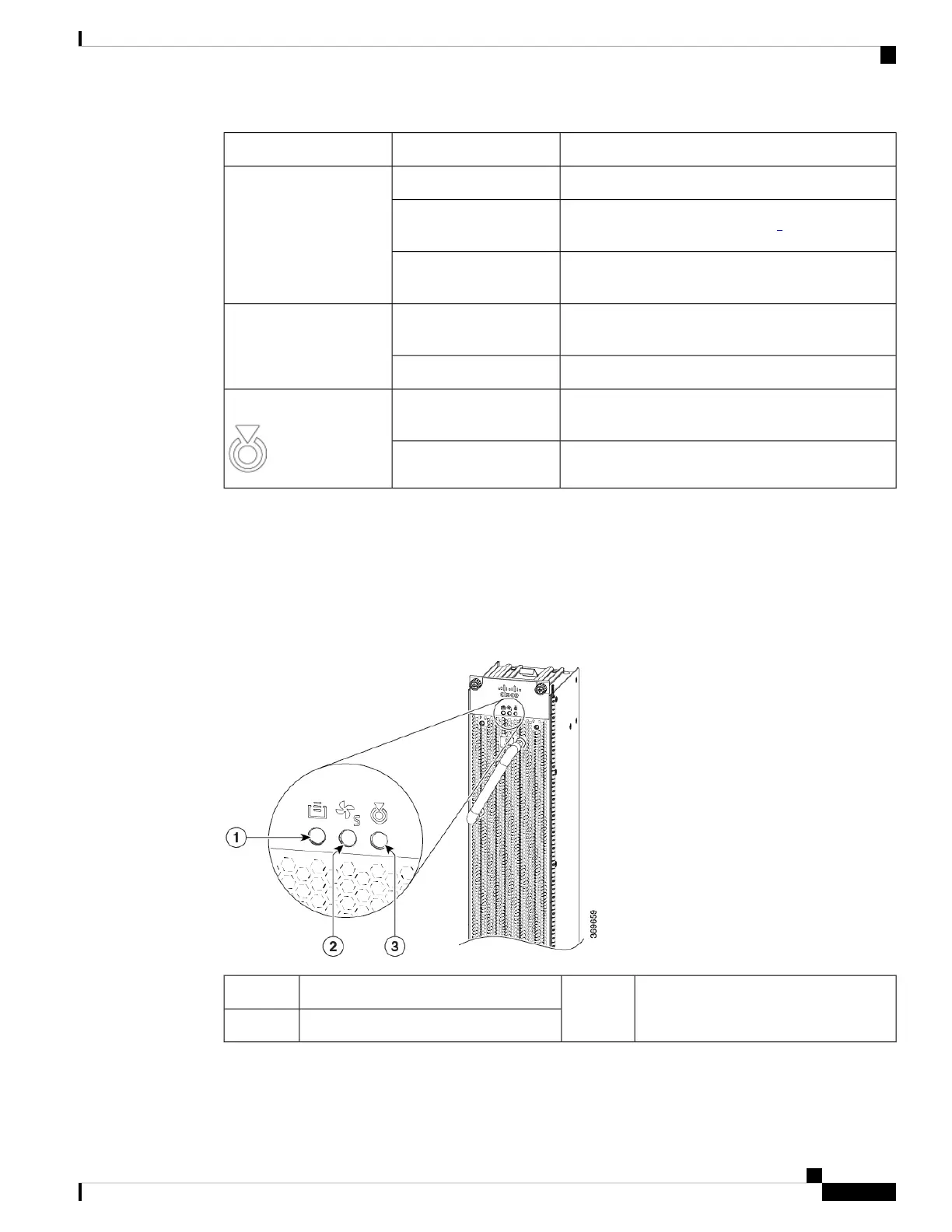
Fan Tray LEDs
The fan tray LEDs are located on the top portion of the module.
Figure 76: Fan Tray LEDs
ATTN (Attention)3FC STS (Status)1
FT STS (Status)2
Hardware Installation Guide for Cisco 8800 Series Routers
99
LEDs
Fan Tray LEDs
 Loading...