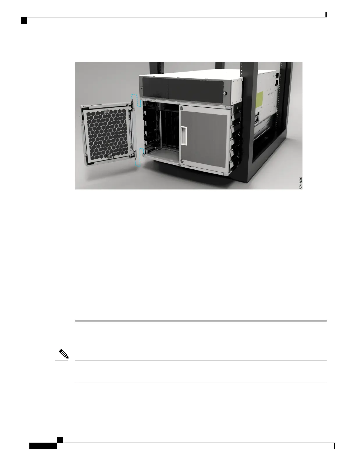
Figure 48: Attach Front Door to 8804 Chassis
Step 4 Now align the spring pin to hole in the top hood and release the spring pin.
Step 5 Ensure the pins are properly inserted into the holes so that the door can freely swing on the spring pins.
Step 6 Repeat Steps 2–5 to install the other front door.
Step 7 Ground the front door.
For information on grounding the front door, see Ground the Front Door, on page 60.
Step 8 Replace the power supply bezel and secure it with the provided jackscrews.
For information on replacing the power supply bezel, see Install Power Shelf Bezel, on page 125.
Install the following modules, if you had them removed from the chassis while mounting into the
rack.
• Fan trays
For more information on replacing components, see Replace a Fan Tray.
Note
Ground the Front Door
To comply with GR-1089, you have to bond the front doors to the ground port on the chassis using the ground
braid.
Note
Hardware Installation Guide for Cisco 8800 Series Routers
60
Unpack and Install the Chassis
Ground the Front Door
 Loading...