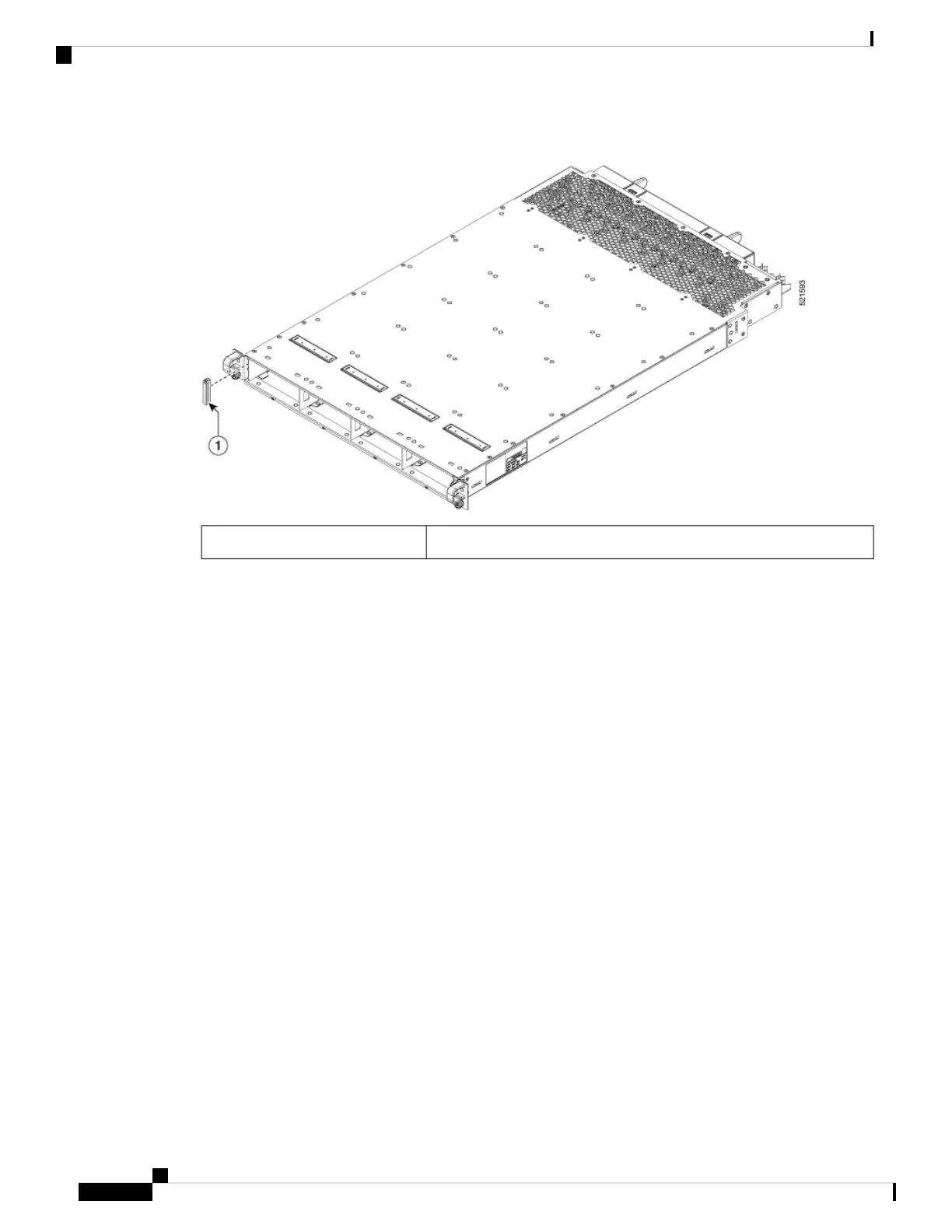
Figure 53: Power Mode Switch Cover
Power mode switch cover.1
Connect DC Power Supply to Power Source
This section contains the procedures to connect the DC source power cables to a DC-powered router.
For DC power cables, we recommend that you use 60A-rated, high-strand-count copper wire cables (#6 AWG
or #4 AWG), or 100A-rated high-strand-count copper wire cables (#2 AWG) . The length of the cables depends
on your router location from the source power. DC power cables are not available from Cisco, but they are
available from any commercial cable vendor.
You must terminate DC power cables using cable lugs at the power tray end. Ensure that the lugs are right-angle
dual-hole and that they fit over to allow quarter inch screws at 0.625-inch (15.88-mm) centers. For #4 AWG
cable, use Panduit part number LCD4-14AF-L or equivalent; for #6 AWG, use Panduit part number
LCD6-14AF-L or equivalent; for #2 AWG cables, use Panduit part number LCD2-14AF-Q or equivalent.
If you are not using power redundancy or are using n+1 power redundancy, you can connect all the power
supplies in the chassis to the same power grid on the rear end of each power tray. If you are using n+n power
redundancy, connect one redundant grid to one of the power supply inputs and the other redundant grid to the
other power supply input on the back of the power tray as shown for each power supply.
The color coding of source DC power cable leads depends on the color coding of the site DC power source.
Ensure that power source cables are connected to the power module with the proper positive (+) and negative
(–) polarity:
• After powering on the router, you should see an LED (for each input) light up green on each power shelf.
If LEDs light up red that indicates that the polarity is incorrect.
This figure shows the lug type required for DC input cable connections.
Hardware Installation Guide for Cisco 8800 Series Routers
66
Powering on the Router
Connect DC Power Supply to Power Source
 Loading...