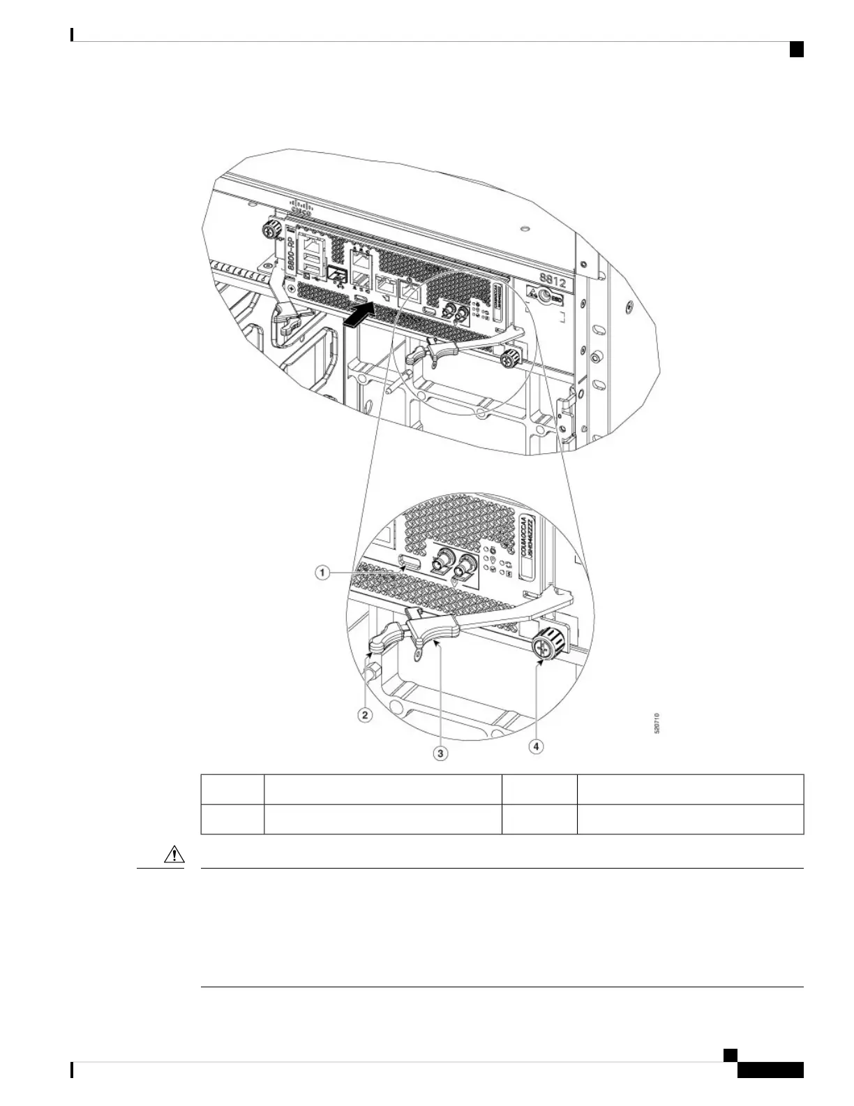
Figure 80: Route Processor Card Components
Laching Mechanism3Latch Lock1
Captive Screw4Ejector Lever Handle2
Unlatching the right ejector lever, so that it disengages from the latch lock (Callout 1 in above figure) triggers
graceful shutdown of the Route Processor if the card is up. If the card shuts down then wait for the Route
Processor status LED to turn off before proceeding.
Moving the latch to the side does not disengage the latch from the lock. This is a safeguard mechanism if an
operator initiated shutdown of the route processor has not been performed before opening the levers. The
ejector open will be logged.
Caution
Hardware Installation Guide for Cisco 8800 Series Routers
111
Replace Chassis Components
Replace a Route Processor Card

 Loading...