• Grasp the optical connector only by the housing to plug or unplug a fiber-optic cable.
The transceiver modules and fiber connectors are keyed to prevent incorrect insertion.
Note
The multiple-fiber push-on (MPO) connectors on the optical transceivers support network interface cables
with either physical contact (PC) or ultra-physical contact (UPC) flat polished face types. The MPO connectors
on the optical transceivers do not support network interface cables with an angle-polished contact (APC) face
type.
Note
Inspect the MPO connector for the correct cable type, cleanliness, and any damage. For complete information
on inspecting and cleaning fiber-optic connections, see the Inspection and Cleaning Procedures for Fiber-Optic
Connections document.
Note
Procedure
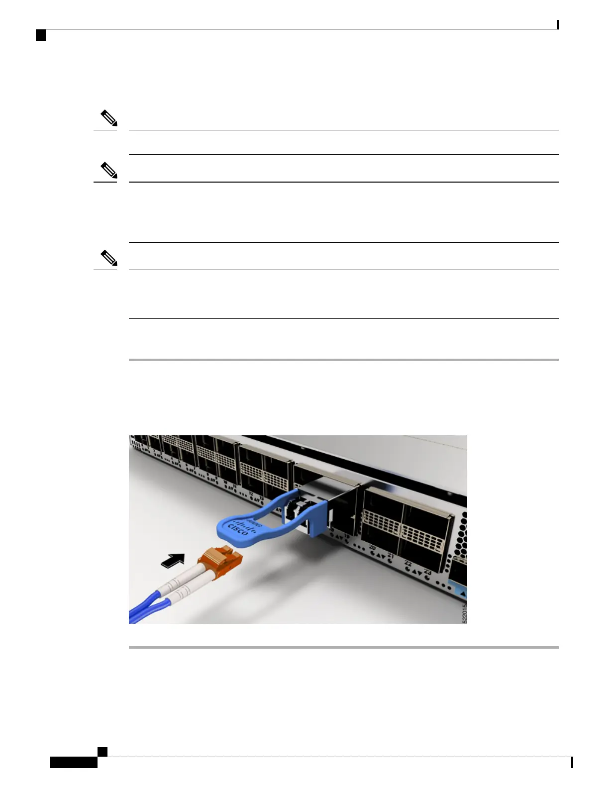
Step 1 Remove the dust plugs from the optical network interface cable MPO connectors and from the transceiver
module optical bores. Save the dust plugs for future use.
Step 2 Attach the network interface cable MPO connectors immediately to the transceiver module.
Figure 73: Cabling a Transceiver Module
Hardware Installation Guide for Cisco 8800 Series Routers
84
Connect Router to the Network
Attach the Optical Network Cable
 Loading...