7-10
Cisco ASR 1000 Series Aggregation Services Routers Hardware Installation Guide
OL-13208-09
Chapter 7 Cisco ASR 1004 Router Overview and Installation
Attaching the Chassis Rack-Mount Brackets
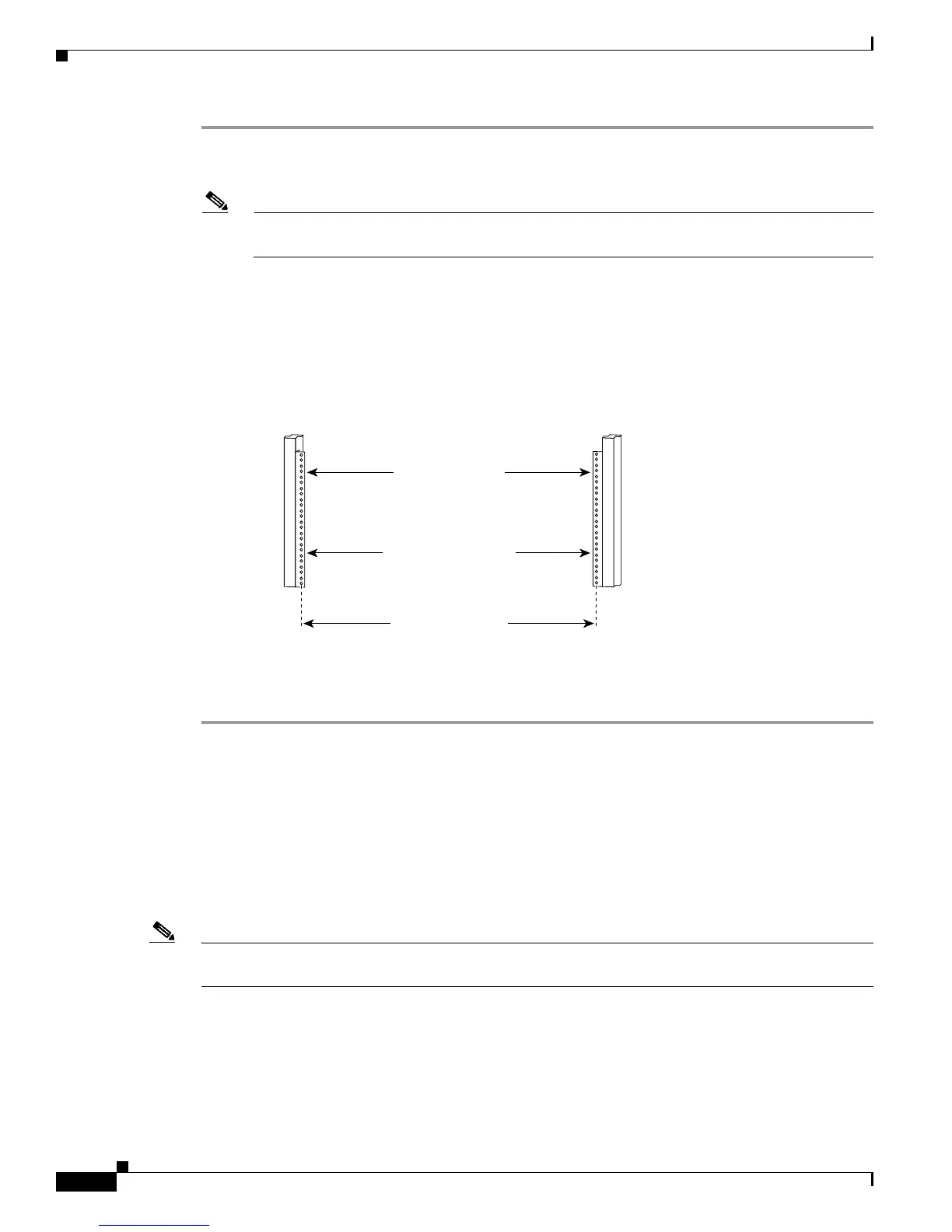
Step 1 Mark and measure the distance between two holes on the left and right mounting rails.
The distance should measure 18.31 inches ± 0.06 inches (46.5 cm ± 0.15 cm).
Note Measure for pairs of holes near the bottom, middle and top of the equipment rack to ensure that
the rack posts are parallel.
Step 2 Measure the space between the inner edges of the left front and right front mounting flanges on the
equipment rack.
The space must be at least 17.7 inches (45 cm) to accommodate the chassis which is
17.25 inches (43.8 cm) wide and fits between the mounting posts on the rack.
Figure 7-7 Verifying Equipment Rack Dimensions
Attaching the Chassis Rack-Mount Brackets
This section explains how to attach the front and rear rack-mount brackets to the chassis. Before
installing the chassis in the rack, you must install the rack-mount brackets on each side of the chassis.
The parts and tools required for installing the rack-mount brackets and cable-management brackets are
listed in the “Tools and Equipment” section on page 5-23.
Note The cable-management brackets are installed on the chassis after you install the chassis rack-mount
brackets and mount the chassis in the rack.
Minimum usable
aperture 17.7 inches
(45.0 cm)
Hole centerline
to hole centerline
18.31 inches ± 0.06 inches
(46.5 cm ± 0.15 cm)
Mounting flanges
28014
 Loading...


