7-19
Cisco ASR 1000 Series Aggregation Services Routers Hardware Installation Guide
OL-13208-09
Chapter 7 Cisco ASR 1004 Router Overview and Installation
Attaching the Cable-Management Bracket
Step 4 Attach the grounding lug with the wire on the left to avoid having the grounding wire overlapping the
power supply. Figure 7-13 shows how to attach the grounding screws.
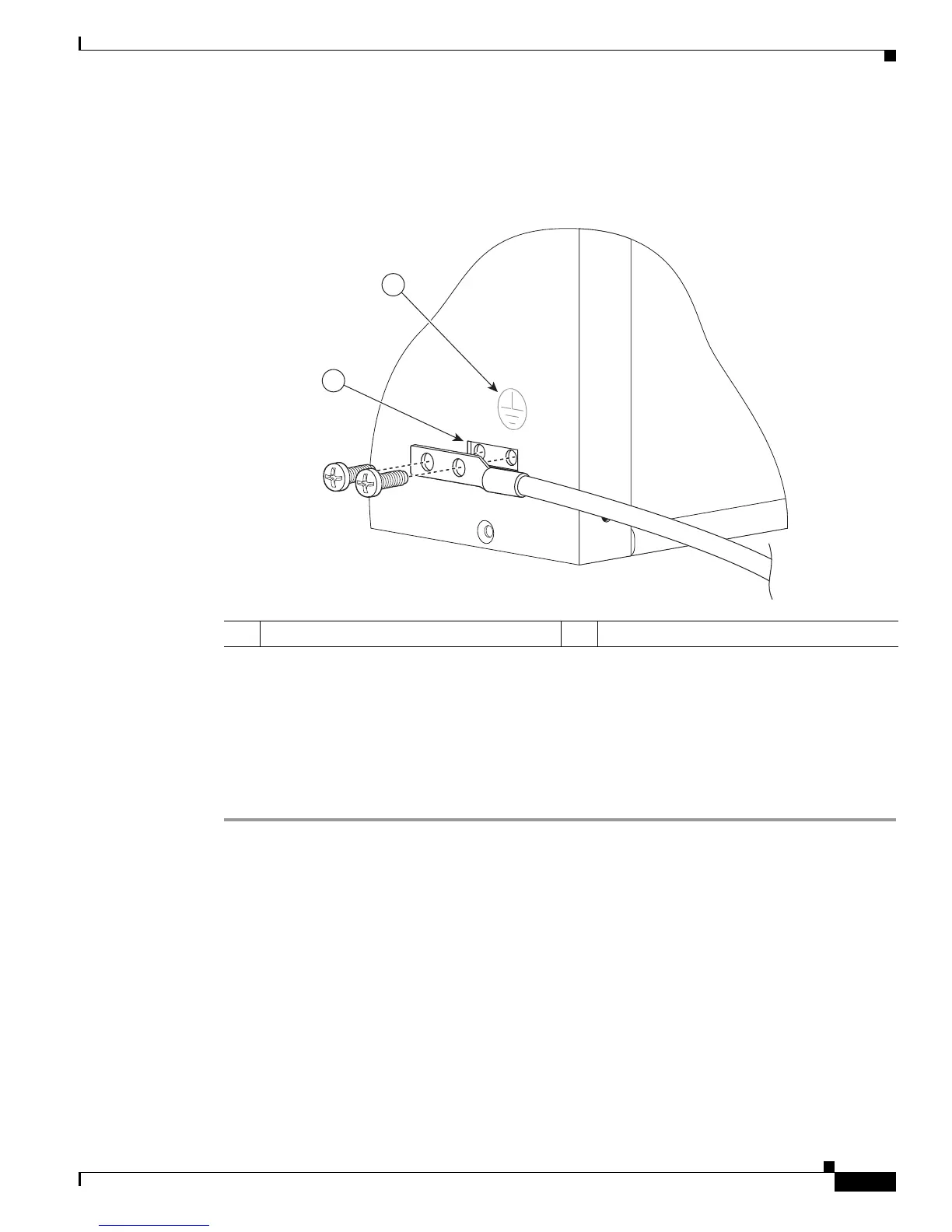
Figure 7-13 Attaching a Grounding Lug to the Chassis Ground Connector
Step 5
Locate the chassis ground connector on the side of your chassis.
Step 6 Insert the two screws through the holes in the grounding lug as shown in Figure 7-13.
Step 7 Use the Number 2 Phillips screwdriver to carefully tighten the screws until the grounding lug is held
firmly to the chassis. Do not overtighten the screws.
Step 8 Connect the opposite end of the grounding wire to the appropriate grounding point at your site to ensure
an adequate chassis ground.
This completes the procedure for attaching a chassis ground connection. To continue, go to the
“Attaching the Cable-Management Bracket” section on page 7-19.
Attaching the Cable-Management Bracket
The cable-management brackets mount to each rack-mount bracket on the chassis to provide
cable-management to both sides of the chassis (parallel with card orientation). These brackets are screw
mounted to the rack-mount brackets to allow easy installation and removal of cables.
1 Chassis ground connector 2 Ground symbol
 Loading...


