7-9
Cisco ASR 1000 Series Aggregation Services Routers Hardware Installation Guide
OL-13208-09
Chapter 7 Cisco ASR 1004 Router Overview and Installation
Rack-Mounting the Cisco ASR 1004 Router
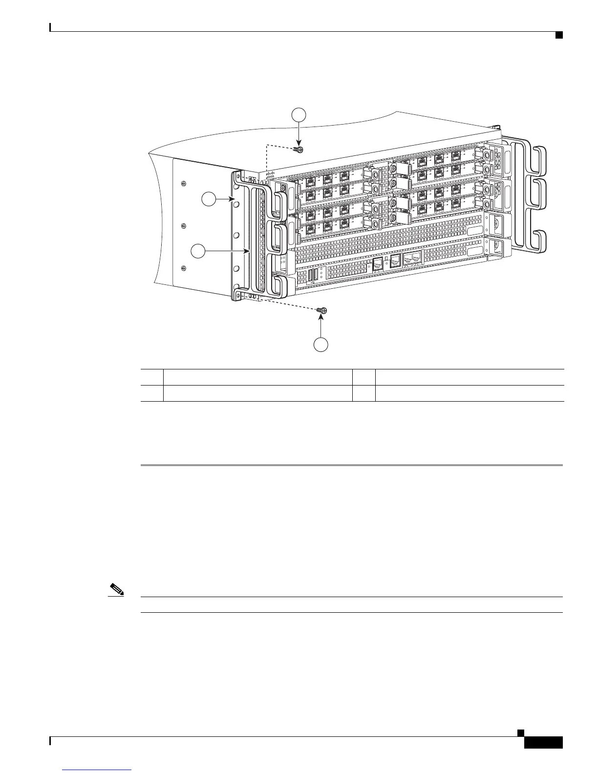
Figure 7-6 Attaching the Cable-Management Brackets to the Cisco ASR 1004 Router
Step 6
Screw the cable-management bracket to each side of the rack-mount brackets already attached to the
chassis. Use two screws for each cable-management bracket. Use the package of four screws.
Step 7 Check that all screws are securely tightened.
You have completed a tabletop or equipment shelf chassis installation. Go to the “Attaching a Chassis
Ground Connection” section on page 7-17 to continue the installation.
Rack-Mounting the Cisco ASR 1004 Router
The Cisco ASR 1004 Router can be installed with both front or rear rack-mount brackets.
Note The chassis rack-mounting flanges are secured directly to the chassis before you lift it into the rack.
Verifying Rack Dimensions
Before you install the chassis, measure the space between the vertical mounting flanges (rails) on your
equipment rack to verify that the rack conforms to the measurements shown in Figure 7-7.
1 Cable-management bracket screws 3 Chassis front rack-mount bracket ear
2 Cable-management bracket — —
280176
SPA-4XO
C3
-
POS
S
TATUS
0
1
2
3
C/
A
A
/L
C
/
A
A
/L
C/
A
A
/L
C/A
A
/L
SPA-4
X
O
C3
-
P
O
S
S
T
AT
US
0
1
2
3
C/A
A
/L
C/
A
A
/L
C/A
A
/L
C
/A
A/L
S
PA
-4
X
O
C3
-
POS
S
TATUS
0
1
2
3
C/
A
A
/L
C/A
A
/
L
C/A
A
/
L
C/A
A/L
SPA
-4
X
OC3
-
P
O
S
S
T
AT
US
0
1
2
3
C/
A
A
/L
C/A
A
/
L
C/A
A
/L
C/A
A/L
S
PA
-
4
X
O
C
3
-PO
S
S
TATUS
0
1
2
3
C/A
A
/L
C/A
A
/
L
C/A
A
/
L
C
/A
A/L
S
PA
-
4
X
O
C
3
-P
O
S
S
T
AT
US
0
1
2
3
C/A
A
/
L
C
/A
A
/
L
C/A
A
/L
C
/
A
A
/L
S
PA
-4
X
O
C
3
-
P
O
S
S
TATUS
0
1
2
3
C/
A
A
/L
C
/A
A
/
L
C/A
A
/
L
C/A
A
/L
SPA
-4
X
O
C
3
-
P
O
S
S
T
AT
US
0
1
2
3
C/
A
A
/L
C/A
A
/
L
C/A
A
/
L
C/
A
A/L
1
1
MI
N
AC
O
MA
J
STBY
A
C
TV
S
TAT
ASR1000-
R
P
1
P
WR
C
R
I
T
B
I
TS
C
O
N
A
UX
CARRIER
LI
N
K
M
G
M
T
ETH
E
R
N
ET
DIS
K
HD
USB
DF
0
1
3
2
 Loading...


