7-31
Cisco ASR 1000 Series Aggregation Services Routers Hardware Installation Guide
OL-13208-09
Chapter 7 Cisco ASR 1004 Router Overview and Installation
Auxiliary Connection
• To reduce the chance of interference, avoid crossing high-power lines with any interface cables.
• Verify all cabling limitations (particularly distance) before powering on the system.
Auxiliary Connection
This asynchronous EIA/TIA-232 serial port (AUX) is used to connect a modem to the Cisco ASR 1000
Series Route Processor 1 for remote administrative access. Use the following procedure to connect the
Cisco ASR 1004 Router to a modem.
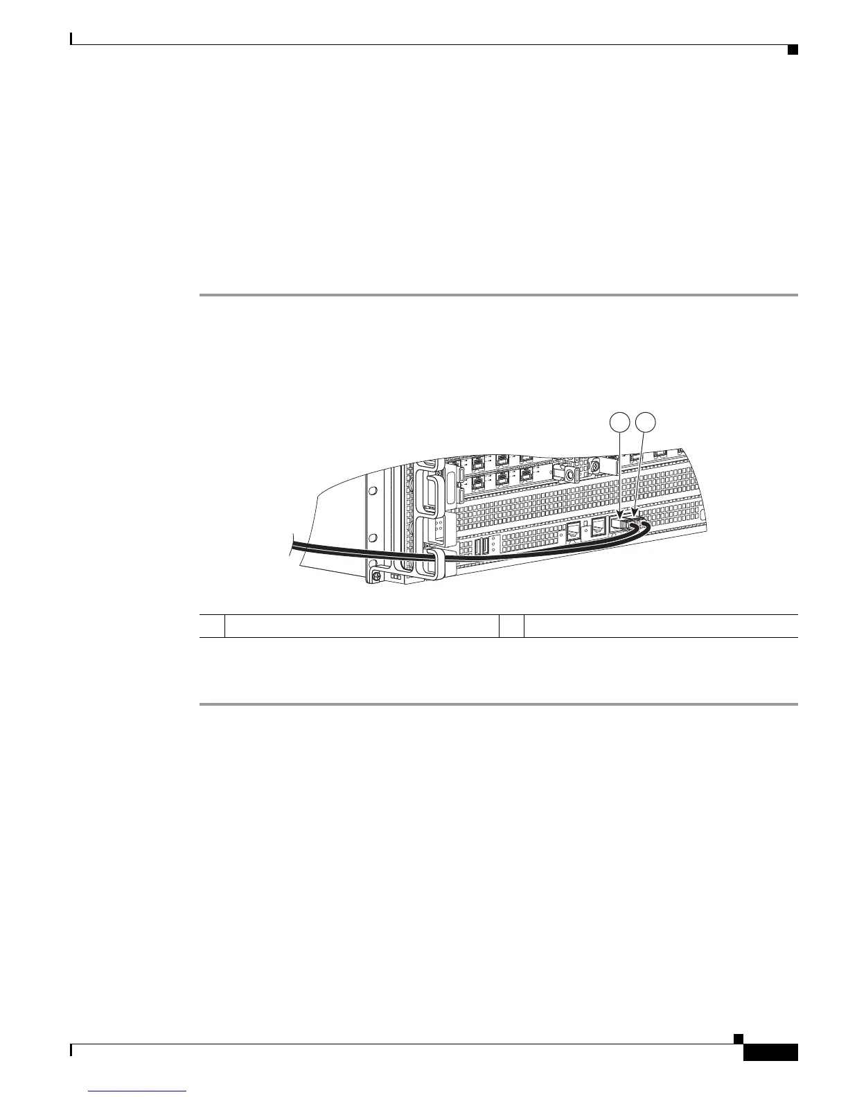
Step 1 Connect one end of the modem cable to the RJ-45 port on the primary Cisco ASR 1000 Series Route
Processor 1, labeled AUX.
Figure 7-23 shows the route processor auxiliary connector.
Figure 7-23 Cisco ASR 1000 Series Route Processor Auxiliary Connector
Step 2
Run the cable up and through the cable-management bracket and connect the other end of the cable to
your modem.
If you have completed all cable connections, go to Chapter 12, “Cisco ASR 1000 Series Routers Power
Up and Initial Configuration.”
1 CON port connection 2 AUX port connection
MI
N
A
C
O
MA
J
STB
Y
A
C
T
V
S
TA
T
ASR100
0-R
P
1
P
WR
C
R
I
T
0
S
PA
-
4
X
O
C3
-
P
O
S
0
1
2
3
A
A
/
L
C/A
A
/L
C/A
A/L
S
PA
-
4
X
O
C
3
-P
O
S
S
TATUS
0
1
2
3
C/
A
A
/L
C/A
A
/
L
C/A
A
/
L
C/A
A
/L
S
PA
-
4
X
O
C
3
-P
O
S
S
T
AT
US
0
1
2
3
C/
A
A
/L
C/A
A
/
L
C/A
A
/
L
C
/
A
A/L
B
I
T
S
C
O
N
A
UX
CA
RR
IER
LIN
K
M
GMT
ET
H
E
R
N
E
T
DISK
HD
USB
DF
0
1
280181
1 2
 Loading...


