7-21
Cisco ASR 1000 Series Aggregation Services Routers Hardware Installation Guide
OL-13208-09
Chapter 7 Cisco ASR 1004 Router Overview and Installation
Connecting the Shared Port Adapter Cables
Step 3 Using the bottom rack-mount ear hole, insert the screw through cable-management bracket and into the
chassis rack-mount (see Figure 7-14).
This completes the procedure for installing the cable-management brackets on the chassis in a rack.
Connecting the Shared Port Adapter Cables
The instructions for connecting the cables for the shared port adapter installed in the Cisco ASR 1004
Router are contained in the respective configuration documents for each port adapter. For example, if
you are connecting the optical fiber cables for the PA-POS-OC3 port adapter, see PA-POS-OC3 Port
Adapter Installation and Configuration at the following location:
http://www.cisco.com/en/US/partner/docs/interfaces_modules/port_adapters/install_upgrade/pos/pa-po
s-oc3_install_config/paposoc3.html
Connecting the Console and Auxiliary Port Cables
The Cisco ASR 1004 Router has a DCE-mode console port for connecting a console terminal and a
DTE-mode auxiliary port for connecting a modem or other DCE device (such as another router) to your
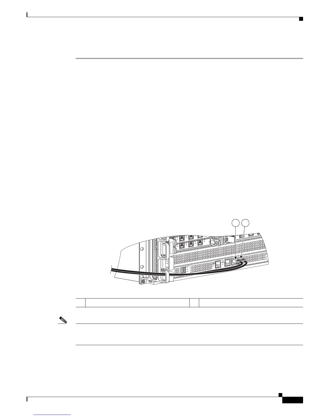
chassis. Figure 7-15 shows the CON and AUX ports on the Cisco ASR 1000 Series route processor.
.
Figure 7-15 Cisco ASR 1000 Series Route Processor—CON and AUX Ports
Note Both the console and the auxiliary ports are asynchronous serial ports; any devices connected to these
ports must be capable of asynchronous transmission. (Asynchronous is the most common type of serial
device; for example, most modems are asynchronous devices.)
The Cisco ASR 1004 Router uses RJ-45 ports for both the auxiliary port and the console port.
For console and auxiliary port pinouts for the RJ-45 connector, see “Cisco ASR 1004 Router
Specifications” section on page A-5. Both ports are configured as asynchronous serial ports.
MI
N
A
C
O
MA
J
STB
Y
A
C
T
V
S
TA
T
ASR100
0-R
P
1
P
WR
C
R
I
T
0
S
PA
-
4
X
O
C3
-
P
O
S
0
1
2
3
A
A
/
L
C/A
A
/L
C/A
A/L
S
PA
-4
X
O
C
3
-P
O
S
S
TATUS
0
1
2
3
C/
A
A
/L
C/A
A
/
L
C/A
A
/
L
C/A
A
/L
S
PA
-4
X
O
C
3
-P
O
S
S
T
AT
US
0
1
2
3
C/
A
A
/L
C/A
A
/
L
C/A
A
/
L
C/
A
A/L
B
I
T
S
C
O
N
A
UX
CA
RR
IER
LIN
K
M
GMT
ET
H
E
R
N
E
T
DISK
HD
USB
DF
0
1
1 Console port - CON 2 Auxiliary port - AUX
 Loading...


